


The first part explained which pin has which meaning on the ESP8266 NodeMCU and connected the first components. In this 2nd part the necessary cables are connected which are needed for the servo controller and the motor driver to control the motors. Also here we go together step by step through the wiring of the individual components. The next step is to connect the motor driver to the servo controller.
Connect motor driver to servo controller
The motor driver has six connections. These have the designation ENA, IN1, IN2, IN3, IN4 and ENB. The direction of rotation of the motors and the speed, for example, are controlled via these six connections.
Motors Speed control
Two DC motors can be connected to the L298N motor driver. A PWM signal is applied to the ENA and ENB pins to allow them to rotate at different speeds. This PWM signal is generated by the servo controller. This allows the motors to be controlled so that they rotate quickly from standstill to the maximum number of revolutions.
Motors Control direction of rotation
If the direction of rotation is to be controlled so that, for example, the robot car can also drive backwards, pins IN1 to IN4 come into play. Pins IN1 and IN2 are relevant for motor 1 and pins IN3 and IN4 for motor 2.
In the following, the control is explained using motor 1 as an example. Depending on whether a HIGH signal is applied to IN1 or IN2, the motor rotates forwards or backwards. If there is a HIGH signal at IN1 and IN2, the motor is short-circuited and a kind of motor brake is achieved. In this case no PWM signal should be present at pin ENA. If IN1 and IN2 are low then the motor stops and does not rotate.
Cabling between motor driver and servo controller
The following table shows the wiring of the motor driver. Since the PCA9685 servo controller can be controlled to output a low (0) or high (1) signal, this function can be used to control the direction of rotation of the motors. More about this in the section Programming and here in particular about programming with the PCA9685 Servo Controller.
| L298N motor driver |
ESP8266 servo controller |
| ENA | Kanal 0 |
| IN1 | Kanal 1 |
| IN2 | Kanal 2 |
| IN3 | Kanal 3 |
| IN4 | Kanal 4 |
| ENB | Kanal 5 |
Six female-to-female jumper cables are used to establish the connection. Now the setup in the robot car looks as shown below.
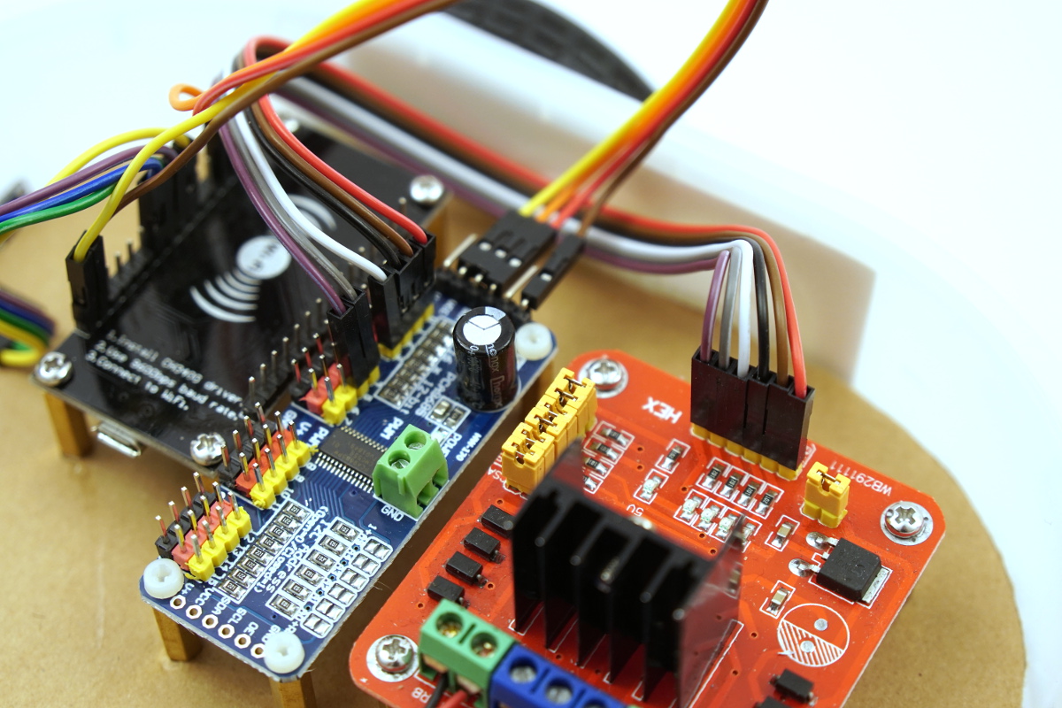
ESP8266 NodeMCU robot car PCA9685 L298N H-Bridge
Connecting motors to the motor driver
The motors must be connected to the motor driver. For this purpose, the motor on the left side is connected as motor 1. The motor of the right side of the robot car as motor 2. It is important that the cables of the colours are connected reversed. So the colours of motor 1 and motor 2 are swapped in the sense of the colours and how the motor is installed in the robot car. The background is that the motors should turn in the same direction. If this is not the case and the robot car for example is turning in a circle when it is supposed to drive forward then the cables of the motor that turns in the wrong direction have to be changed here.
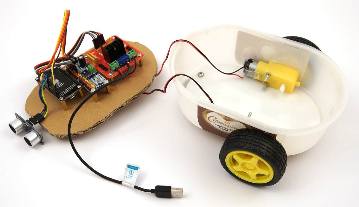
ESP8266 NodeMCU robot car dc motor wiring
Now the logical wiring of the electronic components has been completed and the power supply of the robot car still has to be established.
Establish power supply
The only thing missing is the USB cable which is cut off to supply the motor driver with +5V / GND so that the motors can turn. Old USB cables can be found at the local recycling center in the container for electronic waste. Here you can cut the USB cable from an old keyboard. Now you can see the four wires of the USB cable. The red cable is for the +5V and the black one is the GND cable. These two cables, red and black, are the cables that are needed. The white and green wires are the wires for the data and these are not needed. Therefore they can be cut off as close as possible.
The following picture shows the black cut off USB cable as I connected it to the motor driver.
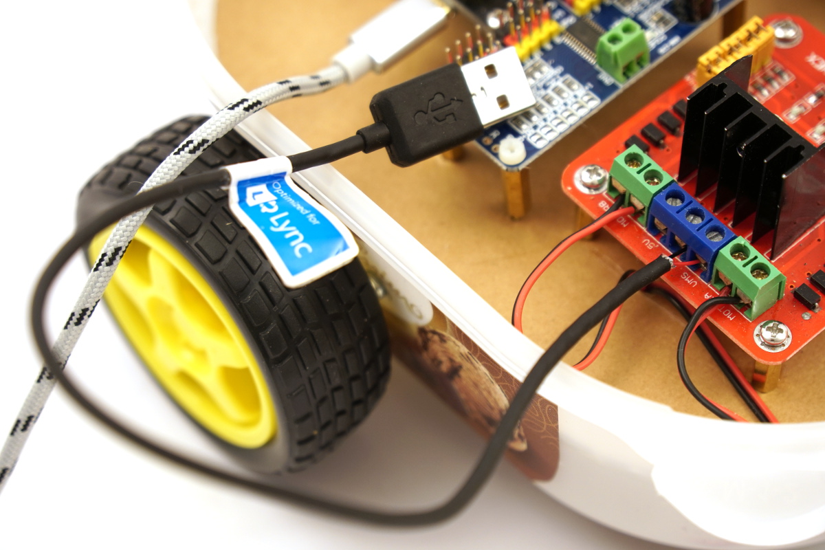
ESP8266 NodeMCU robot car micro usb cable
Summary
Now all cables are connected and the robot car is ready to drive. The software for controlling the robot car is still missing and has to be installed on the ESP8266 NodeMCU. For this to work, the ESP8266 NodeMCU must be connected to the PC with a micro USB cable. You can read more about how this works in the next report.
Article Overview ESP8266 NodeMCU Robot Car:
Building robots with the ESP8266 development board – IntroductionBuilding robots with the ESP8266 development board – Power supply
Building robots with the ESP8266 development board – Components
Building robots with the ESP8266 development board – chassis
Building robots with the ESP8266 development board – Wiring Part 1
Building robots with the ESP8266 development board – Wiring Part 2
Building robots with the ESP8266 development board – Setting up the Arduino development environment
Building robots with the ESP8266 development board – Ultrasonic sensor and motor control
Building robots with the ESP8266 development board – WIFI remote control
Building robots with the ESP8266 development board – servo motor control
Building robots with the ESP8266 development board – OLED display
Building robots with the ESP8266 development board – Magnetometer
Building robots with the ESP8266 development board – GPS receiver introduction
Article Outlook:
Building robots with the ESP8266 development board - GyroscopeBuilding robots with the ESP8266 development board - GPS waypoints
Building robots with the ESP8266 development board - Solar cell


Recent Comments