


In order for the robot to move, the individual components must be connected to each other. The manual leads again step by step through the cabling and shows by means of pictures how and where the cables should be connected. The description of the wiring of the robot car is divided into two parts, so that the text does not become too long and the overview suffers. The description starts with the wiring of the two electric motors.
Wiring the drive motors
Two cables for the power supply must be soldered to the gear motors. It is important that the motors are removed from the yellow plastic gearbox before soldering the cables. Otherwise, the housing of the geared motors may be slightly damaged when using a hot soldering iron. Therefore, please use pliers to loosen the tab holding the motors firmly in the housing. When the two motors have been removed, please solder one red and one black cable each to the motor and to the respective copper lugs.
Hint: Please make sure that the cables point into the inside of the housing. So not at the edge are
After the cables are soldered on, the motors can be put back into the housing and then they can be firmly installed in the chassis. The following picture shows the two motors with the soldered cables already installed in the robot car chassis.

ESP8266 NodeMCU robot car dc motor mount final
ESP8266 NodeMCU connectors
The developer board ESP8266 NodeMCU has a large number of connectors that are led out as pins through the board. In addition to these pins, there is also a USB interface that can be used to program the ESP8266 chip and to supply power to the robot car.
However, it is important to first understand the meaning of the individual pins. Therefore, the following picture shows the layout of the ESP8266 NodeMCU board and the labeling of the pins. It is best to print out this picture and place it on your desk to quickly check the pin assignment.
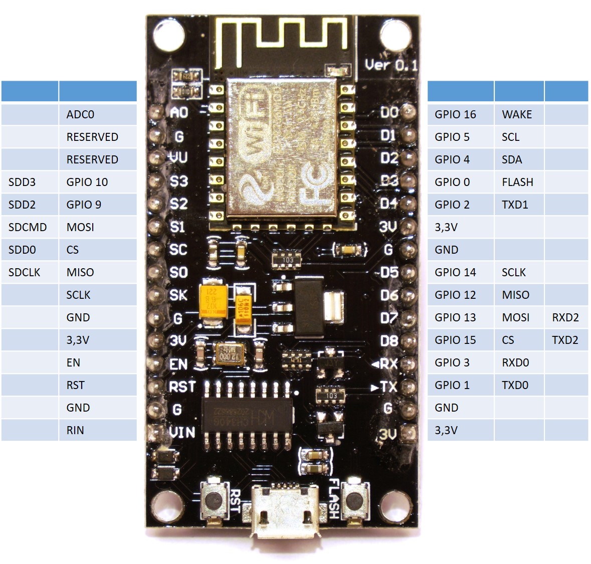
ESP8266 NodeMCU pin number description
Connect ultrasonic sensor to ESP8266
The ultrasonic sensor HC-SR04 has four pins. These are two pins for the power supply with 3.3V to 5V and the GND connection. The other two pins are the trigger pin and echo pin. Via the trigger pin the ultrasonic sensor receives the command to start distance measurement and via the echo pin the measured distance is more or less determined over time. How exactly this works is then described in the chapter Programming the Ultrasonic Sensor.
Below is a small overview of which pin of the ultrasonic sensor is connected to which pin on the ESP8266 NodeMCU.
| ultrasonic sensor HC-SR04 | ESP8266 NodeMCU |
| GND | GND |
| Trig | D5 / GPIO14 |
| Echo | D6 / GPIO12 |
| VIN | 3,3V |
Four female-to-female jumper cables are used to establish the connection. Now the setup in the robot car looks as shown below.
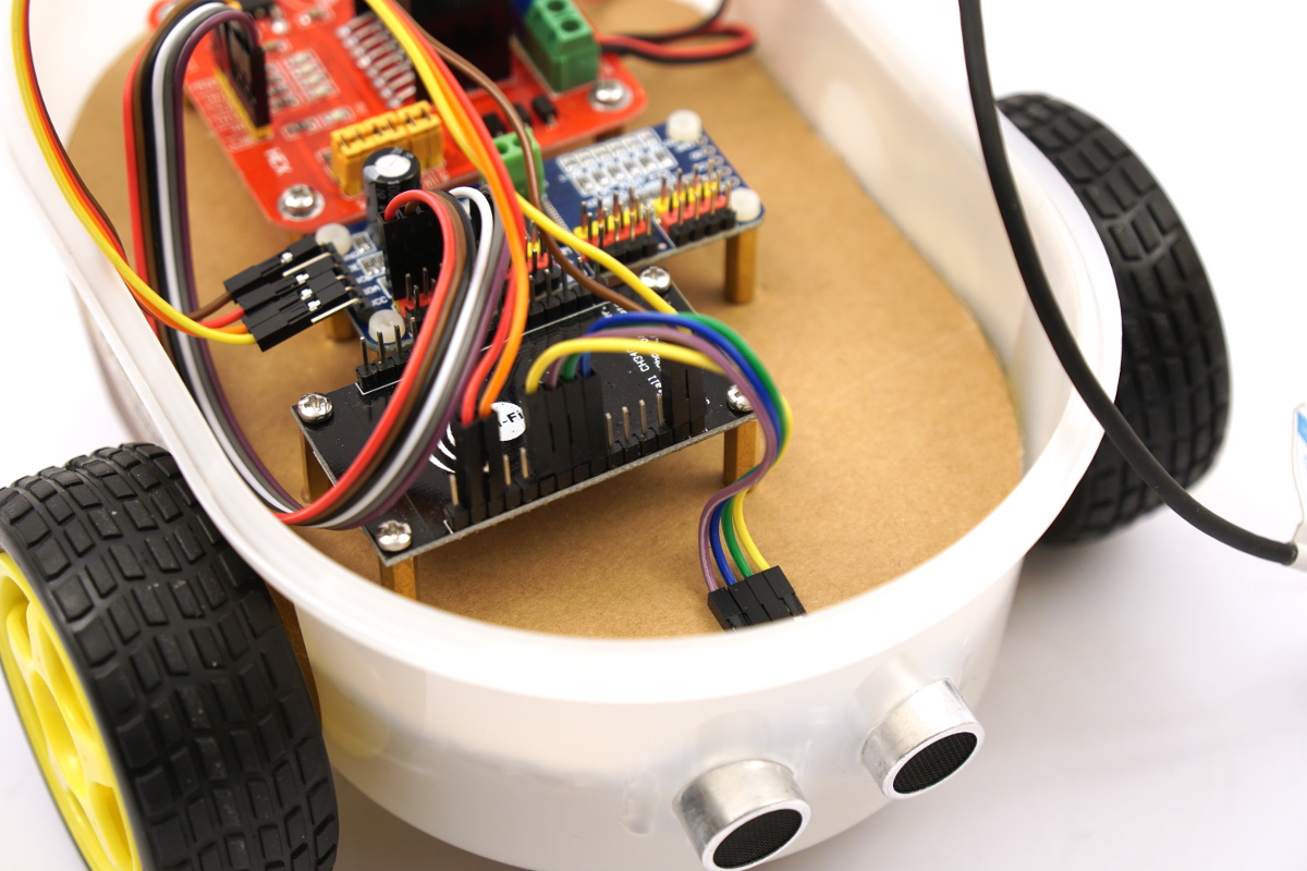
ESP8266 NodeMCU – robot car HS-SR04 ultrasonic sensor
Connecting the servo controller to the I2C bus of ESP8266
The PCA9685 servo controller and the ESP8266 each have an I2C bus. The ESP8266 can communicate with the PCA9685 chip via this I2C bus. This makes it possible to control servo motors, LEDs or, as in this project, a motor driver via the 16 channels of the servo cocking controller.
Below is a small overview of which pin of the servo controller is connected to which pin on the ESP8266 NodeMCU. Four female-to-female jumper cables are used to make the connection.
| PCA9685 servo controller | ESP8266 NodeMCU |
| GND | GND |
| SCL | D1 / GPIO5 |
| SDA | D2 / GPIO4 |
| VIN | 3,3V |
Ready wired and a bit hard to see, the wiring of the servo controller to the ESP8266 in the robot car now looks as shown below.
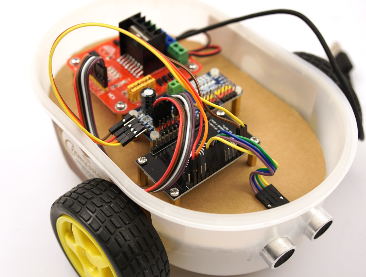
ESP8266 NodeMCU – robot car PCA9685 serco controller
Summary
Important in this first part of the cabling was to understand which pins have which meaning on the ESP8266 NodeMCU board. This is the only way to logically connect the other electronic components to the processing unit and program them later. Then the individual sections explained what has to be connected and how. Now almost all cables are connected and the robot car is almost ready to drive. The cabling of the motor driver with the servo controller is still missing, which is described in part 2.
Article Overview ESP8266 NodeMCU Robot Car:
Building robots with the ESP8266 development board – IntroductionBuilding robots with the ESP8266 development board – Power supply
Building robots with the ESP8266 development board – Components
Building robots with the ESP8266 development board – chassis
Building robots with the ESP8266 development board – Wiring Part 1
Building robots with the ESP8266 development board – Wiring Part 2
Building robots with the ESP8266 development board – Setting up the Arduino development environment
Building robots with the ESP8266 development board – Ultrasonic sensor and motor control
Building robots with the ESP8266 development board – WIFI remote control
Building robots with the ESP8266 development board – servo motor control
Building robots with the ESP8266 development board – OLED display
Building robots with the ESP8266 development board – Magnetometer
Building robots with the ESP8266 development board – GPS receiver introduction
Article Outlook:
Building robots with the ESP8266 development board - GyroscopeBuilding robots with the ESP8266 development board - GPS waypoints
Building robots with the ESP8266 development board - Solar cell


Recent Comments