


I have always used USB GPS receivers with my Raspberry Pi robots. Here in this project I want to create a cheap solution and therefore I use modules that can be connected to a serial interface and cost less than 10,-€ each. Maybe I can’t expect as much from these modules as from a 65,-€ module but to implement the principle of navigation according to GPS coordinates it should be sufficient. I did not buy a very cheap module for this article. Instead I bought a u-blox GPS module GY-NEO6MV2 with the type designation NEO-6M which should work together with the ESP8266 NodeMCU over the serial interface without problems.
My test setup which I use for the first tests before the module is installed in the small robot looks as follows.

ESP8266 NodeMCU robot car gps ublox neo 6m
First, the module must now be connected to the ESP8266 NodeMCU. You can find out how to do this in the following section
Wiring the GPS module
The GPS module is connected to the ESP8266 NodeMCU with four cables once to GND, 3.3V and the two pins GPIO-XX and GPIO-XX. In this way, a serial interface can be implemented via software, as the two pins D1 and D0 typically used are already assigned for communication via I2C.
| ESP8266 NodeMCU | u-blox NEO 6M |
| 3,3V | VCC |
| GND | GND |
| GPIO-14 / D5 (RX) | TX |
| GPIO-12 / D6 (TX) | RX |
If you are not quite sure about the pin assignment of the ESP8266 NodeMCU development board, hopefully the following picture will help you.
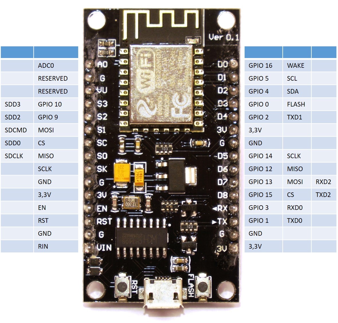
ESP8266 NodeMCU pin number description
Now that the GPS receiver is connected with four female-to-female jumper cables, the first test program can be written. More about this in the following section.
Software
In order for our program to receive and evaluate NMEA data via the serial interface, the “TinyGPS++” library is required and must be installed in the Arduino development environment. Please download the library from the following link.
Download: TinyGPSPlus
After the successful download the library has to be added to the Arduino IDE. To do this, simply load the *.ZIP files via the following menu Sketch>>Include library>>Add .ZIP library.
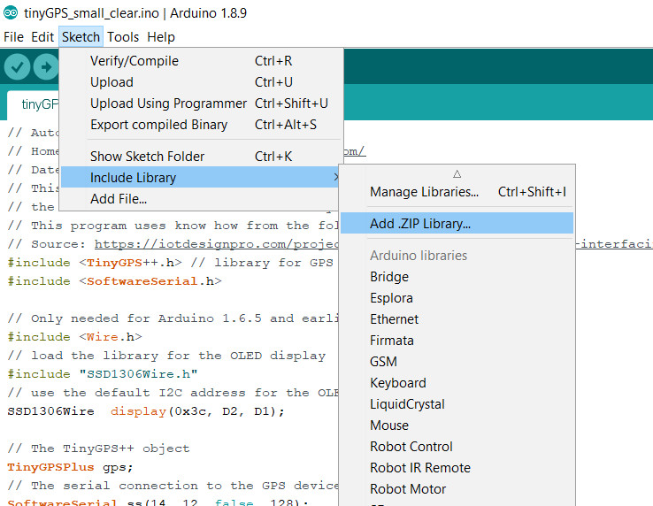
Ardunio IDE add library as ZIP file
The small example program assumes that an OLED display is also connected to the I2C bus and as described in the article Building robots with the ESP8266 development board – OLED display the library for the OLED display is available.
If all prerequisites have been met, the following program can now be transferred to the ESP8266 NodeMCU.
Download: tinyGPS test program
It is best to place the small robot or the experimental setup connected to a power bench in the garden now so that the small GPS antenna has a clear view of the sky.
After about 5 minutes the GPS coordinates should appear on the OLED display. I made the back parts of the GPS information unreadable.

ESP8266 NodeMCU robot car gps ublox neo 6m GPS fix
Zusammenfassung
The small and inexpensive GPS receiver works without problems together with the ESP8266 NodeMCU via the serial software interface. Now it is time to use the NMEA information for navigation. But there is still the problem that the direction to the North Pole cannot be determined yet. For this I had in the article Building robots with the ESP8266 development board – Magnetometer to a magnetometer my experiences already written down.
Article Overview ESP8266 NodeMCU Robot Car:
Building robots with the ESP8266 development board – IntroductionBuilding robots with the ESP8266 development board – Power supply
Building robots with the ESP8266 development board – Components
Building robots with the ESP8266 development board – chassis
Building robots with the ESP8266 development board – Wiring Part 1
Building robots with the ESP8266 development board – Wiring Part 2
Building robots with the ESP8266 development board – Setting up the Arduino development environment
Building robots with the ESP8266 development board – Ultrasonic sensor and motor control
Building robots with the ESP8266 development board – WIFI remote control
Building robots with the ESP8266 development board – servo motor control
Building robots with the ESP8266 development board – OLED display
Building robots with the ESP8266 development board – Magnetometer
Building robots with the ESP8266 development board – GPS receiver introduction
Article Outlook:
Building robots with the ESP8266 development board - GyroscopeBuilding robots with the ESP8266 development board - GPS waypoints
Building robots with the ESP8266 development board - Solar cell


Recent Comments