My goal is to equip the little robot with a GPS receiver so that it can follow GPS waypoints. To make this possible the orientation of the robot to the north pole must be known. Only then the different angles as well as the course angle can be calculated. Therefore I want to install a magnetometer on the robot to know exactly in which direction the front of the robot is pointing. For my robots that use a Raspberry Pi I always use the Raspberry Pi SenseHAT. With this extra SenseHAT I have already realized that my robots are driving to waypoints.
Here in this project with the ESP8266 NodeMCU I want to use a cheap magnetometer. I bought a magnetometer with the chip HMC5883L at Ali Express. There are many manuals for this chipset and again a very good library from Adafruit.
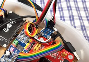
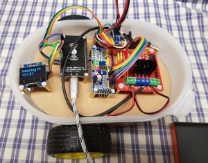
Here a picture how I installed the module in my robot. In this position my concern is that the magnetometer might be disturbed by the closely related modules like the servo controller or motor driver.
Magnetometer wiring
The cabling is actually quite simple again. But since the I2C devices in the small model are getting more and more I built my own I2C Hub. This is quite simple and described in the following article.
Description I2C Hub build by myself:
Connect the magnetometer together with the other devices to the I2C Hub and supply it with 3.3V. This is important because all sensors work with 3.3V and no I2C bidirectional step down converter is built in.
| ESP8266 NodeMCU I2C Bus | Magnetometer I2C Bus |
| 3,3V | 3,3V |
| GND | GND |
| SDA | SDA |
| SCL | SCL |
After everything is wired up the sensor should work. Because I was always not sure if all I2C devices really work I searched the internet for an I2C scanner for the ESP8266 NodeMCU and found a corresponding program. The program can be found on the very good site www.esp8266learning.com under the following link.
http://www.esp8266learning.com/i2c-scanner.php
In the following section, we will try to install the appropriate software on the ESP8266 NodeMCU and see if the north direction is displayed reliably.
Magnetometer software
I always assumed that I bought a magnetometer with the chip HMC5883L at Ali Express. So this one was advertised. Unfortunately the libraries for the HMC5883L together with my module never worked. I searched around for hours, until I found the following page with finally a solution. In short, the cheap magnetometer modules from China are not the advertised HMC5883L chip but the much cheaper MechaQMC5883 chip.
With the example program from Dr. Hans Christian Hillmann (see link above) I could read the first values from the magnetometer.
The program is available for download here: Program QMC5883
How satisfied I was with the results you will find out in the following section.
Magnetometer experience
Unfortunately, I’m quite frustrated. Unfortunately I was never able to read out exactly where north is to be found. I have extended the program of Dr. Hans Christian Hillmann with an OLED display and an attempt to calibrate the magnetometer. But unfortunately I only ever got values that oscillated around 101 or 105 degrees. This is completely useless for my idea of a robot that can track GPS coordinates by car.
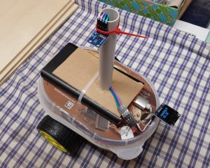
I also changed the position of the module and attached it to a small pole outside the robot car. But also here I could not determine the north direction.
So I have currently given up using the magnetometer. Here the solution is much better with the Raspberry Pi and the possibilities of calibration but the hardware is also much more expensive.
The video shows very well the problem that the north direction was never recognized correctly.
Summary
It was a lot of fun to install the magnetometer into the small robot car and I learned a lot. It’s a pity that I got a magnetometer from China that didn’t have the advertised chipset but a much cheaper one. Thanks to the side of Dr. Hans Christian Hillmann I was able to get this cheap module working anyway. Unfortunately I never managed to determine reliably the north direction and have given up. A solution would be to determine the north direction by using the GPS signal. In this case the robot car would first have to drive a few meters straight ahead for about 5 meters and then you could determine the orientation of the robot car from the received GPS coordinates.
Article Overview ESP8266 NodeMCU Robot Car:
Building robots with the ESP8266 development board – IntroductionBuilding robots with the ESP8266 development board – Power supply
Building robots with the ESP8266 development board – Components
Building robots with the ESP8266 development board – chassis
Building robots with the ESP8266 development board – Wiring Part 1
Building robots with the ESP8266 development board – Wiring Part 2
Building robots with the ESP8266 development board – Setting up the Arduino development environment
Building robots with the ESP8266 development board – Ultrasonic sensor and motor control
Building robots with the ESP8266 development board – WIFI remote control
Building robots with the ESP8266 development board – servo motor control
Building robots with the ESP8266 development board – OLED display
Building robots with the ESP8266 development board – Magnetometer
Building robots with the ESP8266 development board – GPS receiver introduction
Article Outlook:
Building robots with the ESP8266 development board - GyroscopeBuilding robots with the ESP8266 development board - GPS waypoints
Building robots with the ESP8266 development board - Solar cell


Recent Comments