


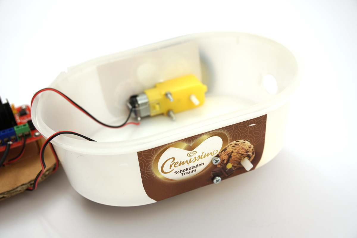
The chassis can be built from many materials. So I made good experiences with chassis which are built up individually from cardboard. However, here the work with scissors and carpet knife is necessary and therefore it can easily come to injuries. Also the construction of a chassis purely from cardboard is very time-consuming and a finished box made of e.g. plastic saves time. Therefore I describe in the following the building of a chassis from an empty ice cream box. This is cheap to have, stable and big enough to accommodate all components of the robot car. Also the thin plastic of the box is easy to work with and in case of errors it can be replaced cheaply.
The picture shows the chassis of the robot car built from an ice cream package.
ESP8266 NodeMCU robot car dc motor wiring
Motors Mounting
The two motors are attached to the left and right sides of the ice pack. It is important that the connecting cables of the motors point into the inside of the packaging, i.e. do not touch the outside of the chassis. Also these small yellow model motors have a small knob on one side which sticks out a little bit. This small knob gives the body additional stability when fixing the motors.
Ideally the motors should be fixed to the chassis in such a way that they are as far forward as possible in the back of the chassis, i.e. to just before the rounding of the plastic box.
ESP8266 NodeMCU robot car dc motor mount
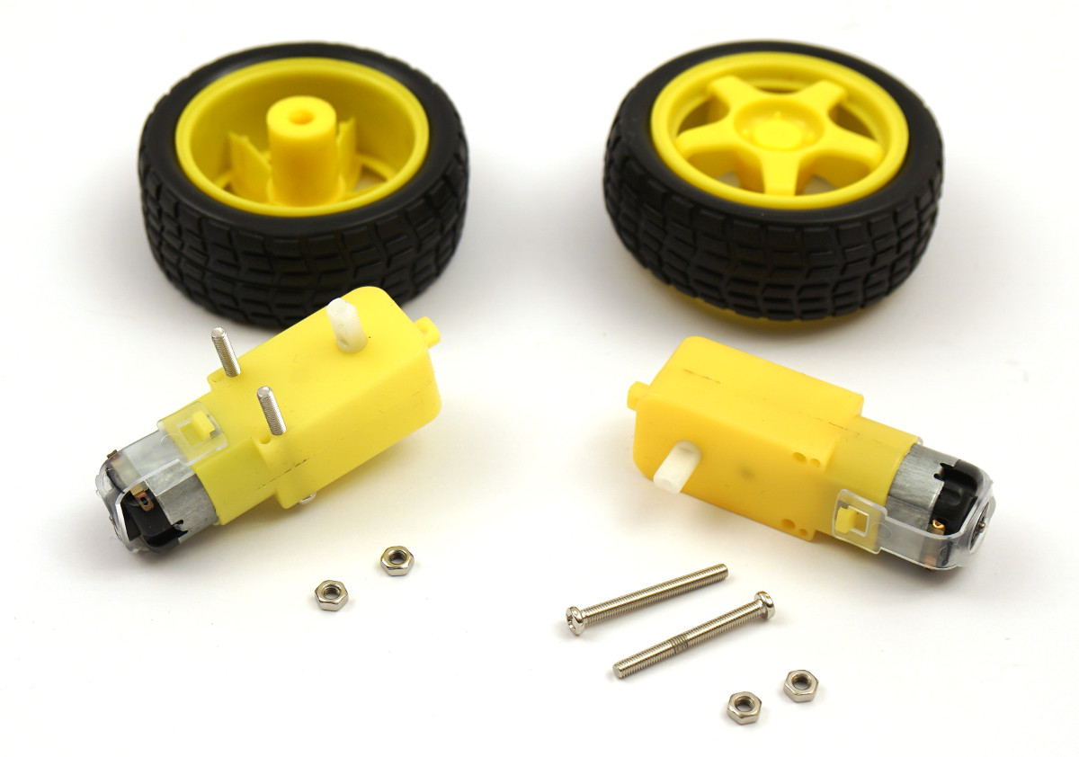
The motors themselves are then each attached to the housing with two M3 threaded screws with a length of approx. 3cm.
ESP8266 NodeMCU robot car dc motor screws
Before the holes in the chassis, i.e. the ice cream packaging, are cut or drilled, they must be measured exactly. Otherwise it will not be possible to fix the motors correctly. It is ideal if a small drilling template is made before drilling the holes. With this template you can check the correct fit of the holes and the marks for the holes can be easily transferred to the chassis.
After the holes in the chassis have been drilled with a 3.5mm drill for the fixing screws and for this small knob with a 3.0mm drill, the motors should be able to be fixed to the chassis as shown below. Since the cables have to be removed again for soldering the cables to the motors, the two motors do not have to be screwed on properly.

ESP8266 NodeMCU robot car dc motor mount final
Attaching the ultrasonic sensor HC-SR04
Ideally, the ultrasonic sensor should be mounted at the front of the chassis, exactly in the middle. Here it is ideal if a hole drill with 16mm is used. Through the holes drilled in this way, the ultrasonic sensor with its transmitter and receiver module can be inserted very well and fixed with some glue from the hot glue gun.
Again, it is worthwhile to create a small drilling template to ensure that the holes are correctly positioned.

ESP8266 NodeMCU robot car HC-SR04 front
Attaching electronic components
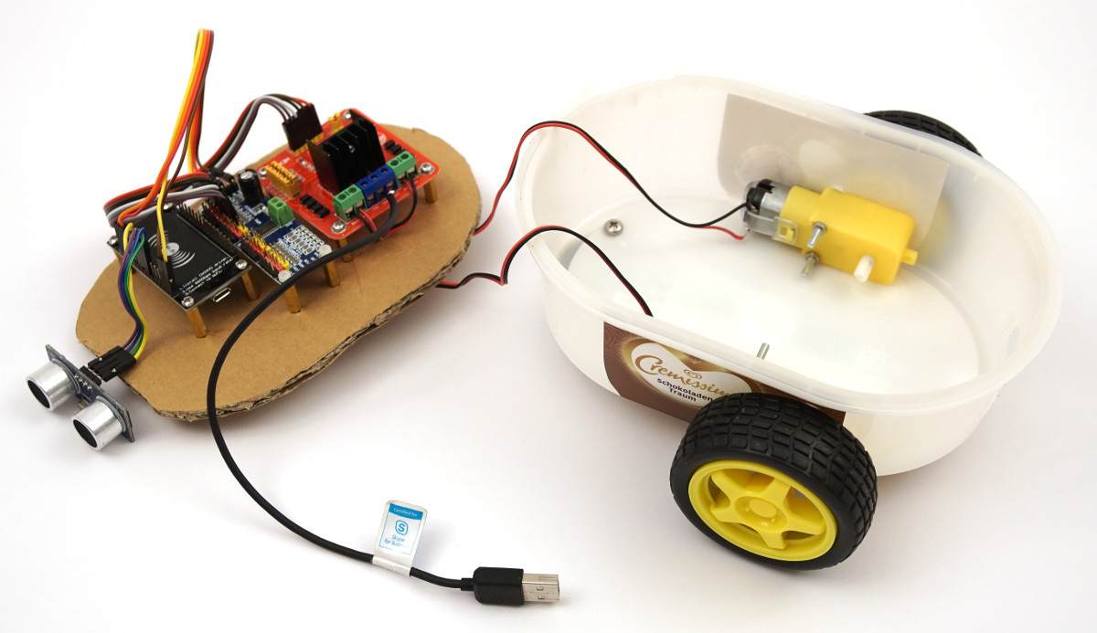
The remaining electronic components are mounted on a piece of cardboard that fits into the chassis. These components include the motor driver, the servo controller and the ESP8266 NodeMCU. The piece of cardboard fits exactly into the ice cream box and rests on the two motors. Once assembled, the electronics carrier in the chassis now looks like this.

ESP8266 NodeMCU robot car electronics
Summary
The remaining electronic components are mounted on a piece of cardboard that fits into the chassis. These components include the motor driver, the servo controller and the ESP8266 NodeMCU. The piece of cardboard fits exactly into the ice cream box and rests on the two motors. Once assembled, the electronics carrier in the chassis now looks like this.
Article Overview ESP8266 NodeMCU Robot Car:
Building robots with the ESP8266 development board – IntroductionBuilding robots with the ESP8266 development board – Power supply
Building robots with the ESP8266 development board – Components
Building robots with the ESP8266 development board – chassis
Building robots with the ESP8266 development board – Wiring Part 1
Building robots with the ESP8266 development board – Wiring Part 2
Building robots with the ESP8266 development board – Setting up the Arduino development environment
Building robots with the ESP8266 development board – Ultrasonic sensor and motor control
Building robots with the ESP8266 development board – WIFI remote control
Building robots with the ESP8266 development board – servo motor control
Building robots with the ESP8266 development board – OLED display
Building robots with the ESP8266 development board – Magnetometer
Building robots with the ESP8266 development board – GPS receiver introduction
Article Outlook:
Building robots with the ESP8266 development board - GyroscopeBuilding robots with the ESP8266 development board - GPS waypoints
Building robots with the ESP8266 development board - Solar cell


Recent Comments