


Until now, two DC motors in the robot car were controlled by an L298N motor driver. But with the built-in servo controller much more is possible because it still has many free connections. For example, a servo motor can be connected to one of these free connections. Servo motors are quite normal in robots like humanoid robots and are indispensable in model making. So the steering of classic RC model cars is always controlled by a servo motor. Therefore I would like to explain how a servo motor can be controlled with the ESP8266 NodeMCU and a PCA9685 servo controller.
So first a small servo motor is needed and an additional two wire cable to connect the servo controller to a 5V voltage in our robot car. Without this additional power supply on the servo controller, the servo motor cannot rotate.
The following picture shows the robot car and the small servo motor I have connected to the servo controller.
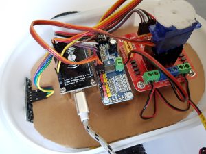
ESP8266 NodeMCU robot car servo motor
List of materials
As always, I add the links to the Amazon web shop here. Who wants to buy larger quantities to keep the costs low should do this best directly in China, e.g. via Ali-Express.

The cable that is still needed is not listed here. I assume that a short cable will already be available. If not then I recommend the following cable which I use again and again in my models.

Cabling
To supply the servo controller with a 5V voltage I recommend to connect a cable to the terminal marked with V+ and GND of the servo controller. The other end of the cable should be connected to the motor driver in addition to the already connected and cut off USB cable. In this way the servo controller receives a voltage of 5V via the connection on the motor driver. Since most servo motors work with 5V, this solution is ideal.
In the following picture you can see the cable standing up in a wide arc.
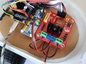
ESP8266 NodeMCU robot car PCA9685 power wire
The servo motor with its cable is connected to channel 8 of the servo controller. Army please make sure that the dark cable of the 3-pin connector is connected to the pin of channel 8 which is marked GND / black. In the middle is the 5V line which is mostly red and the brighter yellow / orange third line is for the PWM signal. The PWM signal tells the servo motor how far it should turn.
The following picture shows the colours of the cable coming from the servo motor and connected to the colour coded connector on the servo controller.
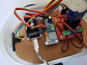
ESP8266 NodeMCU robot car servo motor
Programming servo motor control
The programming is actually quite simple again. As a basis for my small program and the control of a servo motor I used an Adafruit example program again. With this small program as a basis the control of the servo motor on channel 8 was very easy.
The program is available for download here: servo-test.zip
Video
The video is not very exciting but shows how the engine turns using the small program.

Summary
I hope the small manual was written understandably and it is now clear how to control a servo motor. From now on it should be possible for you to write your own individual program that raises and lowers e.g. a brush that is mounted on the robot. It would also be possible to mount the ultrasonic sensor on the servo motor to explore the environment around the robot car. But this only makes sense if there is a gyroscope in the robot car to be able to turn the robot car exactly in a certain direction.
Article Overview ESP8266 NodeMCU Robot Car:
Building robots with the ESP8266 development board – IntroductionBuilding robots with the ESP8266 development board – Power supply
Building robots with the ESP8266 development board – Components
Building robots with the ESP8266 development board – chassis
Building robots with the ESP8266 development board – Wiring Part 1
Building robots with the ESP8266 development board – Wiring Part 2
Building robots with the ESP8266 development board – Setting up the Arduino development environment
Building robots with the ESP8266 development board – Ultrasonic sensor and motor control
Building robots with the ESP8266 development board – WIFI remote control
Building robots with the ESP8266 development board – servo motor control
Building robots with the ESP8266 development board – OLED display
Building robots with the ESP8266 development board – Magnetometer
Building robots with the ESP8266 development board – GPS receiver introduction
Article Outlook:
Building robots with the ESP8266 development board - GyroscopeBuilding robots with the ESP8266 development board - GPS waypoints
Building robots with the ESP8266 development board - Solar cell


Recent Comments