


Now that the live video image of the camera is transmitted over the network, this article is about activating the I2C bus of the ESP32-CAM. The I2C bus is needed to connect e.g. an I2C OLED display or a PCA9685 servo controller in the robot car. Only with a PCA9685 servo controller and a L298N H-bridge it is possible to make the motors of the robot car turn at different speeds. This is the only way to control the motors, which makes it possible to drive the robot e.g. through the apartment.
Many pins are no longer free on the ESP32-CAM. But the good news is that it is possible to put the I2C bus on the two RX and TX pins that are only needed for programming the ESP32-CAM. If the ESP32-CAM is not programmed, the two pins can be used for the I2C bus. So it is possible to use the I2C bus and to control a variety of different sensors, drivers and controllers via the I2C bus.
The remaining free pins of the ESP32-CAM are listed in the following table. In the table I have indicated which pins I have already used successfully.
| Pin at ESP32-CAM | tested |
| GPIO1 (TX) | ja |
| GPIO3 (RX) | ja |
| GPIO16 | nein |
The following picture shows on which pins the connectors for the I2C bus on the ESP32-CAM can be found when using the GPIO1 and GPIO3
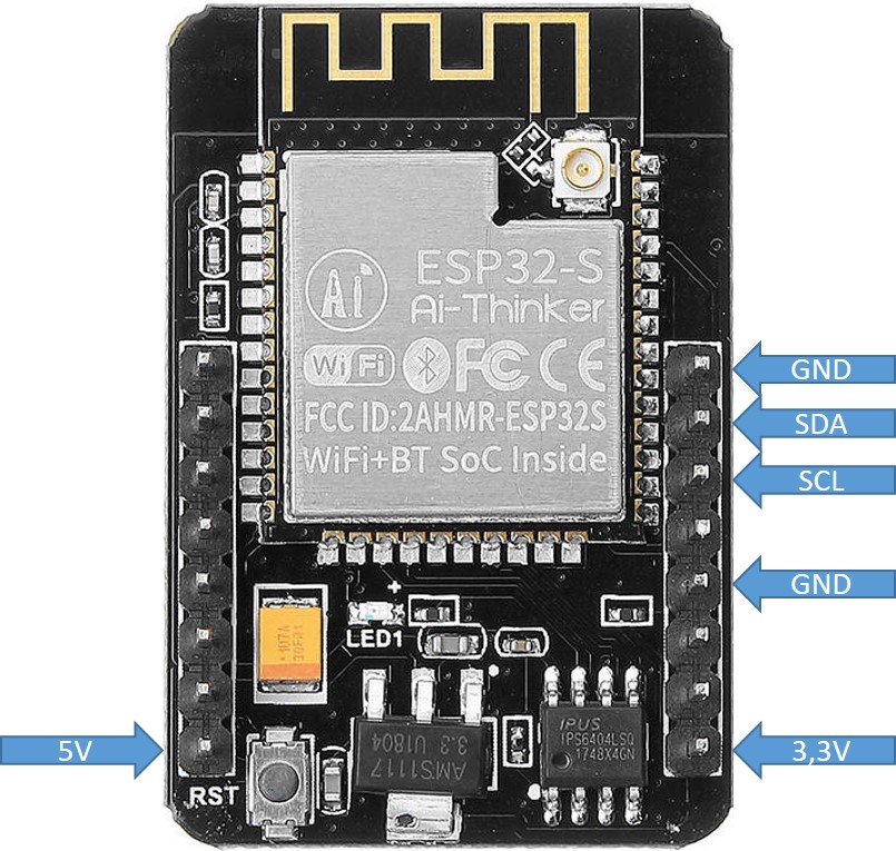
ESP32-CAM I2C connection
Control OLED display via I2C bus
To use the I2C bus we will now use pin 1 and pin 3. This means that in case the ESP32-CAM is to be programmed again, the cables have to be plugged in again so that the USB-Servial Adapter is connected via RX / TX and not the SSD1306 OLED display.
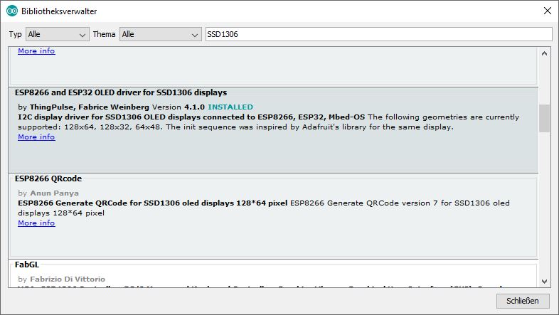
As first device we will connect a SSD1306 OLED display and can test if the I2C bus works at all. In order to control the SSD1306 OLED display, the corresponding library for the OLED display must be installed. Please search for the library with the following keyword “ESP32 OLED” and install it on your PC in the Arduino development environment. After installing this library you can use the OLED display SSD1306.
ESP32-CAM OLED Display SSD1306
The display is connected after the program with the test output for the OLED display has been written to the ESP32-CAM module.
| Pins ESP32-CAM | SSD1306 OLED Display |
| 3,3V | 3,3V |
| GND | GND |
| GPIO1 | SDA |
| GPIO3 | SCL |
Since the SSD1306Wire library allows to specify the pins to be used as SDC and SDA of the I2C bus it is possible to connect a SSD1306 OLED display. I have defined two variables as follows.
#define I2C_SDA 1
#define I2C_SCL 3
Der Aufruf der SSD1306Wire Bibliothek sieht dann im Programm wie folgt aus.
#include "SSD1306Wire.h"
// Initialize the OLED display using Wire library
SSD1306Wire display(0x3c, I2C_SDA, I2C_SCL);
Now everything is prepared so that after programming the ESP32-CAM the OLED display shows something. The output shows the IP address of the ESP32-CAM.
In the following the example program I used for a first test if the OLED display can be controlled via the I2C bus.
Download: CameraWebServer
On the following picture you can see the wired robot car with connected OLED display.
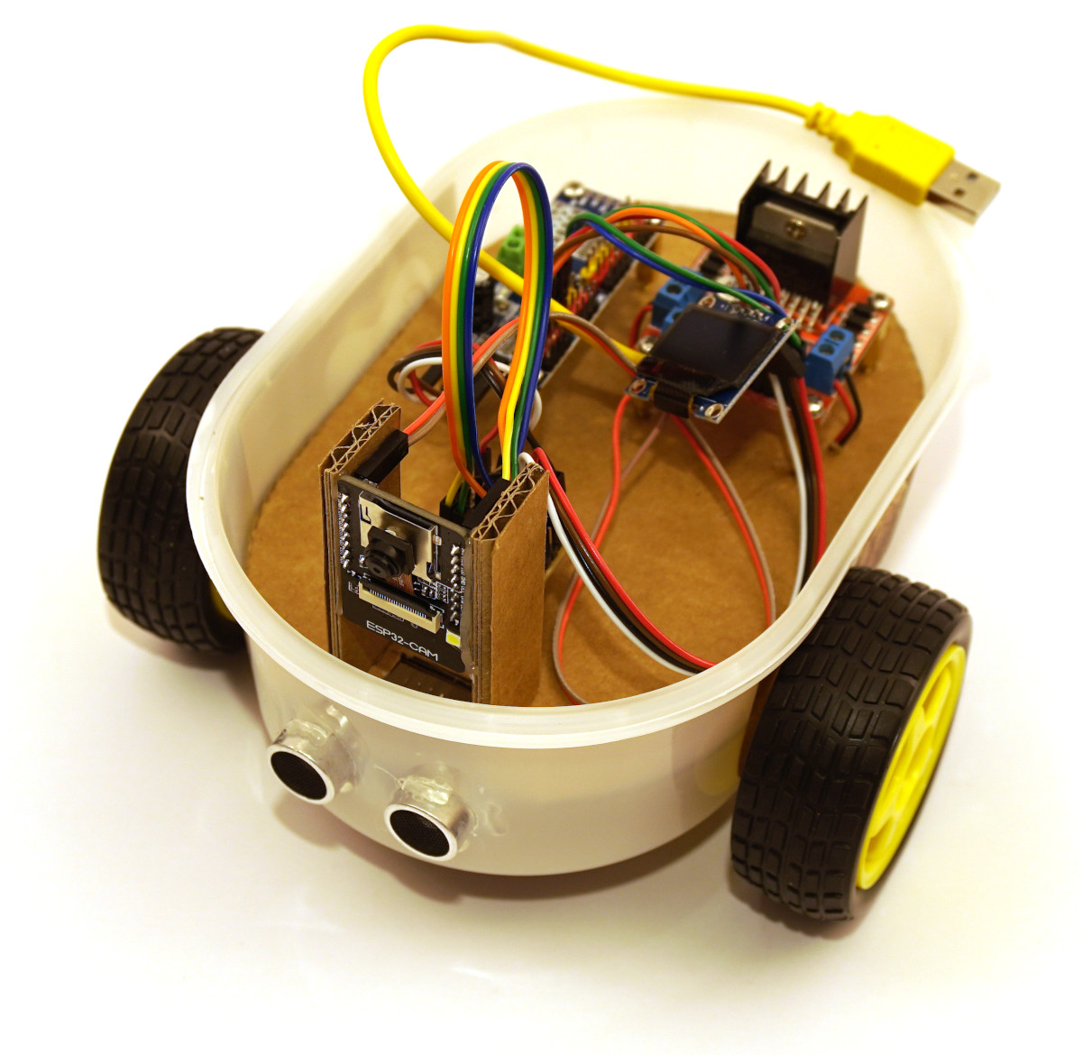
ESP32-CAM OLED display
Summary
If everything worked fine, the OLED display should now show the current IP address of the ESP32-CAM module. If this has worked so far then we now have the certainty that the I2C bus is working and that the servo controller can be connected as a device next. But from now on any other device can be connected to the I2C bus. How this works with the Wire.h library is explained in the next article using the PCA9685 servo controller as an example.


Recent Comments