

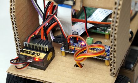
The wiring is the foundation for ensuring that all electronic components of your robot car work together smoothly. In this article, I’ll show you how to set up the ESP32 robot car wiring by connecting the ESP32 to the PCA9685 servo controller, motor driver, OLED display, and LED ring.
Overview of Components
1. ESP32
The ESP32 is the central control module of your robot. All other components are connected to this microcontroller.
2. PCA9685 Servo Controller
This module expands the PWM outputs of your ESP32, enabling precise control of motors and servos.
3. Motor Driver (e.g., L298N)
The motor driver manages the control of the TT geared motors.
4. OLED Display
The display shows the current status of your robot, such as “Controller Connected” or “Motors Stopped.”
5. WS2812 LED Ring
The LED ring provides visual effects such as speed indicators or ambient lighting.

Robot ESP32 – Logical Wiring
Step-by-Step ESP32 Robot Car Wiring Guide
1. Connecting the PCA9685 Servo Controller to the ESP32
The PCA9685 is connected to the ESP32 via the I2C interface:
- SDA (Data Line): Connect the SDA pin of the PCA9685 to GPIO21 of the ESP32.
- SCL (Clock Line): Connect the SCL pin of the PCA9685 to GPIO22 of the ESP32.
- VCC and GND: Connect the PCA9685 power supply to 3.3V (VCC) and GND of the ESP32.

Robot ESP32 PCA9685 I2C Wiring
2. Connecting the Motor Driver to the PCA9685
The PWM outputs of the PCA9685 control the motor driver:
- Connect six PWM channels of the PCA9685 to the inputs of the motor driver (e.g., IN1 to IN4) and ENA and ENB.
| PCA9685 Servo Controller | Motor Driver L298N |
|---|---|
| Channel 0 | ENA |
| Channel 1 | IN1 |
| Channel 2 | IN2 |
| Channel 3 | IN3 |
| Channel 4 | IN4 |
| Channel 5 | ENB |

Robot ESP32 PCA9685 I2C and L298N H-Bridge Wiring
3. Connecting the OLED Display
The OLED display is also controlled via the I2C bus. Since pins 21/22 on the ESP32 are already in use, we use the I2C output on the PCA9685 Servo Controller:
- SDA: Connect the SDA pin of the display to the SDA output of the Servo Controller (shared with the PCA9685).
- SCL: Connect the SCL pin of the display to the SCL output of the Servo Controller.
- VCC and GND: Connect power to 3.3V (VCC) and GND of the Servo Controller.

Robot ESP32 PCA9685 I2C, L298N H-Bridge, and OLED Display Wiring
4. Connecting the LED Ring (WS2812) to the ESP32
The WS2812 LED ring is controlled via a single data pin:
- DIN (Data Line): Connect to GPIO5 of the ESP32.
- VCC and GND: Connect to 5V and GND from a stable power source (e.g., a step-down converter). Avoid using the ESP32’s 3.3V pin due to current limitations.

Robot ESP32 PCA9685 I2C, L298N H-Bridge, OLED Display, and LED Ring Wiring
Important Power Supply Notes
- Shared Ground: All components must share a common ground (GND) to function reliably.
- Voltage Considerations: Power the ESP32 with 3.3V and all other components with their required voltages (e.g., 5V for LED ring and motor driver).
Summary
With this ESP32 robot car wiring setup, all components are properly connected. The PCA9685 handles PWM signals, while the OLED and LED ring give visual feedback. The motor driver controls movement. Now your ESP32 robot is ready for action!
In the next article, I’ll explain how to set up the software to unlock the full functionality of your robot. Have fun tinkering and wiring!
Artikel Übersicht ESP32 Roboter Auto:
ESP32 Dev Kit C V4 – Build Your Own Robot Car – Project KickoffESP32 Dev Kit C V4 – Build Your Own Robot Car – Electronics and Components
ESP32 Dev Kit C V4 – Build Your Own Robot Car – Chassis Examples
ESP32 Dev Kit C V4 – Build Your Own Robot Car – Power Supply
ESP32 Dev Kit C V4 – Build Your Own Robot Car – Power Supply Wiring
ESP32 Dev Kit C V4 – Build Your Own Robot Car – Logical Wiring
ESP32 Dev Kit C V4 – Build Your Own Robot Car – Setting Up the Arduino Development Environment
ESP32 Dev Kit C V4 – Build Your Own Robot Car – The Robot Software


Recent Comments