


To program the ESP32-CAM module, it must first be connected to the PC. As it does not have a USB interface, the USB-Serial Adapter must be used. In the ESP32-CAM module I have listed in the component list there is already such an adapter included in the delivery. I myself have used a similar adapter which I have used in similar projects before. The principle is always the same: ESP-32 with female-to-female jumper cables must first be connected to the USB-Serial Adapter.
The following picture shows which pins have to be connected in which way so that the communication can be done via the serial interface of the ESP32-CAM module.
Note: Please make sure that your USB-Serial adapter supplies the ESP32 with a 3.3V voltage and not 5V. Most adapters have either both voltages or a jumper switch on the board. Supplying the ESP32 with 5V instead of 3.3V may damage the module.

ESP32-CAM serial connection
The following table shows you how the cabling is done on the side of the USB-Serial Adapter.
| ESP32-CAM | USB-serial adapter |
| GND | GND |
| TX | RX |
| RX | TX |
| 3,3V | 3,3V |
It is important that one of the GND contacts is connected to the IO0 pin before ESP32 is switched on for programming. Only then can ESP32 be programmed. The following picture shows the wiring of ESP32 with a USB-Serial adapter. The cabling is always the same, even if the USB-Serial adapter may have a slightly different design.
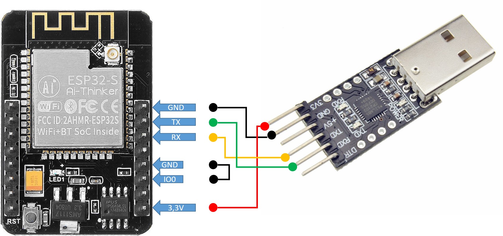
ESP32-CAM serial connection flash mode
I bought a USB-A extension cable to connect the USB-Serial Adapter to my PC more easily. Because it easily happens that after plugging and unplugging several times the female-to-female jumper cables are not really tight anymore.

If you now connect the USB serial adapter with the ESP32 module connected to your PC and start the Arduino development environment the ESP32-CAM module should be recognized. It is now important to select the correct port in the Arduino development environment through which the USB serial adapter can be accessed.
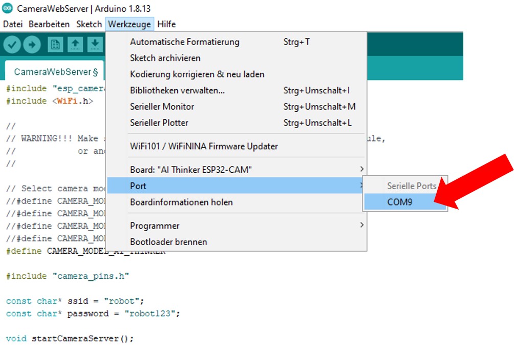
ESP32-CAM Arduino IDE Port
Note: If the ESP32 module is not recognized, there may be a wiring error or a problem with the support of the USB serial adapter on your PC. If the USB-Serial Adapter is not recognized, you may need to install the necessary drivers from the manufacturer.
Summary
In this article you have learned how to connect your ESP32-CAM module to the USB-Serial adapter. Once the USB-Serial Adapter has been recognized on your PC, you have overcome all the hurdles. From now on you can program your ESP32 module and, for example, install the sample program for video streaming. In the following chapter we will flash exactly this small program onto the ESP32-CAM module and watch the first live video stream of the camera.
Article Overview ESP32-CAM Robot Auto:
ESP32-CAM building your own robot car with live video streaming – project startESP32-CAM building your own robot car with live video streaming – Set up development environment
ESP32-CAM building your own robot car with live video streaming – USB-serial adapter wiring
ESP32-CAM building your own robot car with live video streaming – Installing the live video streaming software
ESP32-CAM building your own robot car with live video streaming – Design of the chassis
ESP32-CAM building your own robot car with live video streaming – Cabling in general
ESP32-CAM building your own robot car with live video streaming – Wiring the I²C hub
ESP32-CAM building your own robot car with live video streaming – robo car example programs
ESP32-CAM building your own robot car with live video streaming – programming the WIFI remote control
ESP32-CAM building your own robot car with live video streaming – connect external WIFI antenna


Recent Comments