

In my search for an alternative to the classical ultrasonic sensors I came across the low cost Time of Flight (ToF) sensors from ST. These are soldered directly onto a small circuit board by various suppliers. The connections are led out via this circuit board and the sensor is therefore very easy to connect to a Raspberry Pi or Arduino, for example.
I have chosen the model from Adafruit with the VL53L0X chip. The reason for my decision was mainly the level shifter built in by Adafruit. So the two connectors XSHD and GPIO can be connected directly to the Raspberry Pi. An adjustment of the voltage 3.3V (Raspberry Pi) to 2.8V (VL53L0X) does not need to be made separately.
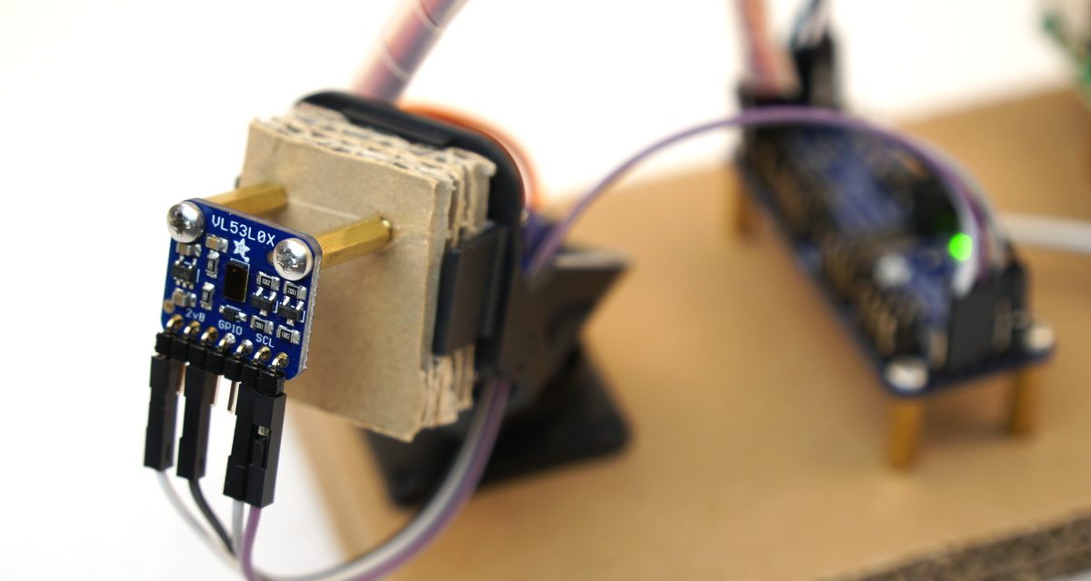
I made a small setup to test the ToF Sensor.
Adafruit VL53L0X laser scanner
List of components
As with almost all my reports, I have published a small list of the components I used here. The links all lead to the Amazon web shop to make it easy to find and purchase the parts.
Tof VL53L0X Sensor
I chose this model from Adafruit because it can easily be connected to the Raspberry Pi via the I2C bus.

Adafruit Servo Controller PCA9685
The Adafruit servo controller has proven itself in many projects.
![Adafruit 16-Channel PWM / Servo HAT for Raspberry Pi - Mini Kit [ADA2327]](https://m.media-amazon.com/images/I/41B1rgSsVHL._SL160_.jpg "Adafruit 16-Channel PWM / Servo HAT for Raspberry Pi - Mini Kit [ADA2327]")
Adafruit mini Pan&Tilt Kit
The mini Pan & Tilt Kit from Adafruit is great for turning the Raspberry Pi camera on the robot in different directions or for turning and tilting the ToF sensor for measurements.

Raspberry Pi 3 Model B+
I always recommend to buy the most powerful Raspberry Pi Model B+. But the setup shown here works with all other models as well.

Micro SD-Karte
microSDXC Speicherkarte + Adapter bis zu 100 MB/Sek., Class 10, U1, A1,Grau, Rot")
The Female 2 Female, screws and USB cable are not listed here.
Cabling
How to connect the ToF sensor and the servo controller to the I2C bus is not explained in detail. My setup starts at the I2C bus of the Raspberry Pi, then goes to the servo controller and from there at the end of the servo controller to the VL53L0X sensor. Thus the ToF VL53L0X sensor and the PCA9685 servo controller operate at 3.3V. The extra power supply of the servo motors on the servo controller is provided by the extra 5V connections.
Software Installation
How to connect the ToF sensor and the servo controller to the I2C bus is not explained in detail. My setup starts at the I2C bus of the Raspberry Pi, then goes to the servo controller and from there at the end of the servo controller to the VL53L0X sensor. Thus the ToF VL53L0X sensor and the PCA9685 servo controller operate at 3.3V. The extra power supply of the servo motors on the servo controller is provided by the extra 5V connections.
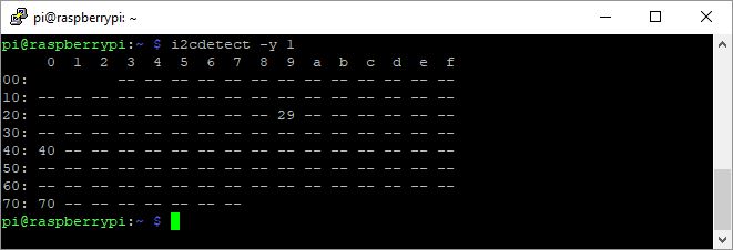
Adafruit VL53L0X I2C Bus
VL53L0X Python Software Installation
I also chose the model from Adafruit, because the online shop and electronics supplier Pimoroni has put a great Python library online that can be used to control the VL53L0X sensor. This library can be found under the following link:
URL: https://github.com/pimoroni/VL53L0X-python
Next you install the Python software. This should already be there if you are using the latest Raspbian version.
Command: sudo apt-get install build-essential python-dev
After installing Python, you will now clone the Pimoroni repository to your SD card. To do this, create a folder with the name VL53L0X in your home directory “home/pi”.
Then change to this folder you created and execute the following command.
Command: git clone https://github.com/naisy/VL53L0X_rasp_python.git
After cloning the repository to your SD card you have to “install” it. To do this, change to the subdirectory “VL53L0X_rasp_python” and execute the make command.
Command: make
After completing the command, you can run the example programs that are now on your SD card and display the first measured values.
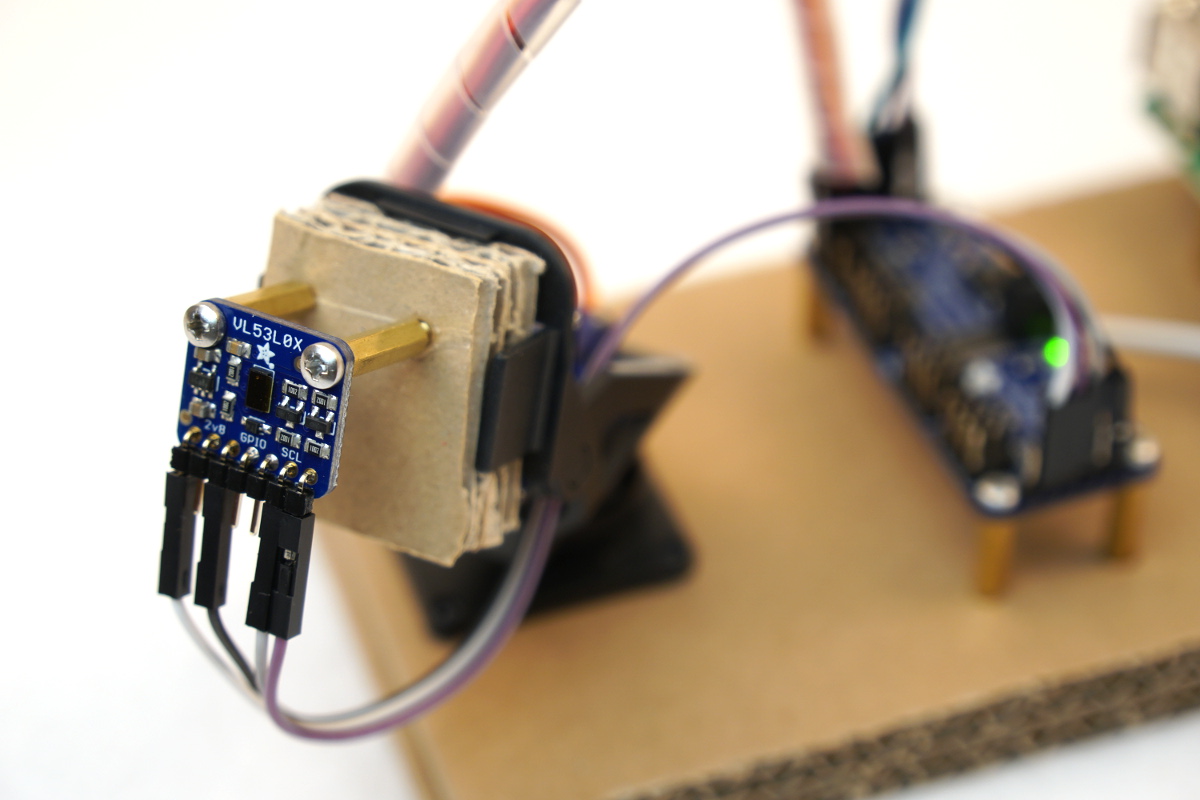
Adafruit VL53L0X sensor modul
Adafruit Mini Pan-Tilt Kit and PCA9685
I had bought the ready assembled Adafruit mini Pan&Tilt kite. I then connected this to the Adafruit PCA9685 servo controller. How to install the PCA9685 servo controller under Raspbian is described in the following article.
URL: 16 Channel PCA9685 Servo Controller – Part 2 Software Installation and Test
Now you should also be able to program the Pan&Tilt Kit with the example programs.
Summary
In this blog post I have explained how to connect the ToF Sensor VL53L0X with the Raspberry Pi. Furthermore you are now able to turn and tilt the ToF Sensor with the Pan&Tilt Kit. This enables us to understand the environment more precisely and to scan it.
In another article I will introduce my small Python program and go into more detail about the measured values.
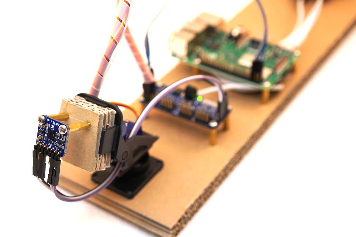
The finished setup of my test setup looks like the picture below.
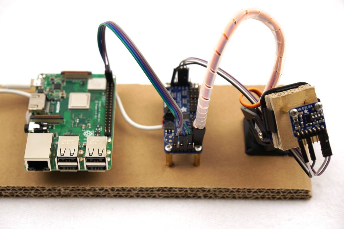
Adafruit VL53L0X laser scanner setup pan tilt kit


Recent Comments