


Ich habe verschiedenste Raspberry Pi Roboter über die letzten Jahre selber gebaut. Alle haben gemeinsam, dass sie eine L298N H-Brücke als Motortreiber einsetzen. Aber um ein sehr exaktes PWM Signal für den Motor Treiber zu erzeugen habe ich mich entschieden, dieses PWM Signal nicht mehr mit dem Raspberry Pi zu generieren. Ich habe mir dafür einen speziellen Kontroller zugelegt der nur dafür da ist ein PWM Signal zu erzeugen. Mit solch einem Kontroller ist es möglich ein sehr genaues PWM Signal zu erzeugen was mit einem Raspberry Pi so nicht möglich ist. Die beste Lösung ist somit ein externes Board, dass über den I2C Bus angesprochen werden kann. Ich habe bei meiner Suche einen Servo Kontroller gefunden mit einem PCA9685 Chip. Dieser Servo Kontroller zusammen mit einer H-Brücke ist eine gute Lösung um ein LED Band zu dimmen. So ist es recht einfach möglich sich seinen eigenen LED Dimmer zu bauen.
Ich habe ein kurzes LED Band an einem Ausgang der L298N H-Brücke angeschlossen. Bei dem LED Band handelt es sich um ein 12V Band. Es ist aber kein RGB LED Band und zeigt somit nur weiß als Leuchtfarbe.
Das folgende Bild zeigt mein Setup mit dem PCA9685 Servo Kontroller, der L298N H-Brücke als LED Treiber für den LED Dimmer. Das LED Band ist auch zu sehen am unteren Bildrand.
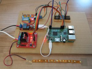
Raspberry Pi – LED dimmer
Das folgende Bild zeigt den Aufbau aktiv mit eingeschalteten LED Dimmer. Das Python Programm das ich entwickelt habe um das LED Band dimmen zu können ist kostenlos verfügbar und wird von mir hier auf meinem Blog weiter unten zum Download angeboten.
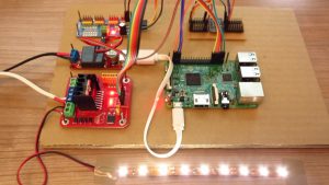
Raspberry Pi – LED dimmer active
List der Komponenten:
Raspberry Pi 3 Model B

I2C Level Konverter von Adafruit
Dieser Level Konverter wird zwischen PCA9685 und dem Raspberry Pi geschalten. So ist der I2C Bus auch für den PCA9685 nutzbar der mit 5,0V arbeitet statt den 3,3V des Raspberry Pi.
L298N H-Bridge als Motor Treiber oder LED Treiber

PCA9685 Servo Kontroller
 16-Channel 12-bit PWM/Servo Driver - I2C interface - PCA9685")
Software PCA9685
Als erstes muss die Adafruit Bibliothek für den PCA9685 Servo Kontroller installiert werden. Mit dem Servo Kontroller wird das PWM Signal für das Dimmen des LED Bandes erzeugt.
Adafruit PCA9685 library
Um die Adafruit Bibliothek für den Servo Kontroller zu installieren müssen eine Reihe von Befehlen im Terminal Fenster ausgeführt werden. Für weiterführende Informationen betreffend der Bibliothek besuche Adafruit auf GitHub.
Adafruit GitHub URL: https://github.com/adafruit/Adafruit_Python_PCA9685
Als Betriebssystem kommt bei mir ein Raspbian Jessie zum Einsatz. Die hier aufgeführten Befehle müssen einer nach dem anderen ausgeführt werden. Ich war dafür über eine SSH Verbindung an meinem Raspberry Pi für die Installation der Programme angemeldet.
Befehl: sudo apt-get install git build-essential python-dev
Befehl: cd ~
Befehl: git clone https://github.com/adafruit/Adafruit_Python_PCA9685.git
Befehl: cd Adafruit_Python_PCA9685
Der folgende Befehl muss im Ordner „Adafruit_Python_PCA9685“ ausgeführt werden in dem die Adafruit Bibliothek liegt. Er installiert die Bibliothek auf Deinem Raspberry Pi.
Befehl: sudo python setup.py install
Nach der Installation der Bibliothek und nach dem alle Kabelverbindungen hergestellt wurden kannst Du jetzt überprüfen ob der Servo Kontroller gefunden wird. Dazu führe den folgenden Befehl im Terminal Fenster aus.
Befehl: sudo i2cdetect -y 1
Der PCA9685 Servo Kontroller sollte mit der Adresse 40 wie bei mir oder einer anderen Adresse am I2C Bus gefunden werden.
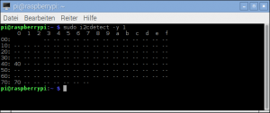
i2c detect bus result
Ich habe ein kleines Python Programm geschrieben mit dem die Helligkeit des LED Bandes kontrolliert werden kann. Das Programm verwendet einen PCA9685 Kontroller und eine L298N H-Brücke als LED Treiber.
Download: Raspberry Pi – LED dimmer
Layout der Verkabelung
Ich habe in Fritzing ein Bild der Verkabelung erstellt. Ich hoffe so ist es klarer was wie verkabelt gehört.
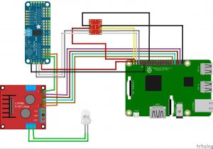
LED dimmer layout
Video LED Dimmer:
Das Video zeigt ein kurzes LED Band das an eine L298N H-Brücke angeschlossen ist. Der PCA9685 Servo Kontroller erzeugt das PWM Signal und steuert die H-Brücke.

Übersicht der PCA9685 Servo Kontroller Anleitungen:
16-Kanal PCA9685 Servo Kontroller - Teil 1 Einführung und Aufbau16-Kanal PCA9685 Servo Kontroller - Teil 2 Software Installation und Test
16-Kanal PCA9685 Servo Kontroller - Teil 3 Ansteuerung einer L298N H-Brücke
16-Kanal PCA9685 Servo Kontroller - Teil 4 Ansteuerung eines LED Bandes mit Dimm-Funktion
16-Kanal PCA9685 Servo Kontroller - Spezial: Raspberry Pi elektronischer Modellbau Fahrtenregler


Recent Comments