


The Raspberry Pi has the I²C bus to which various sensors, OLED displays and e.g. motor drivers can be connected. Since the I²C is led out via two pins, only one device can be connected. However, since more than one device can be operated on the I²C bus, it is a good idea to build an I²C hub yourself. In the following article I explain step by step which materials are needed and how to build such a hub.
The following picture shows the I2C hub I built myself. I left some space to drill four holes in the small board to be able to fix the hub to the robot car with four screws.
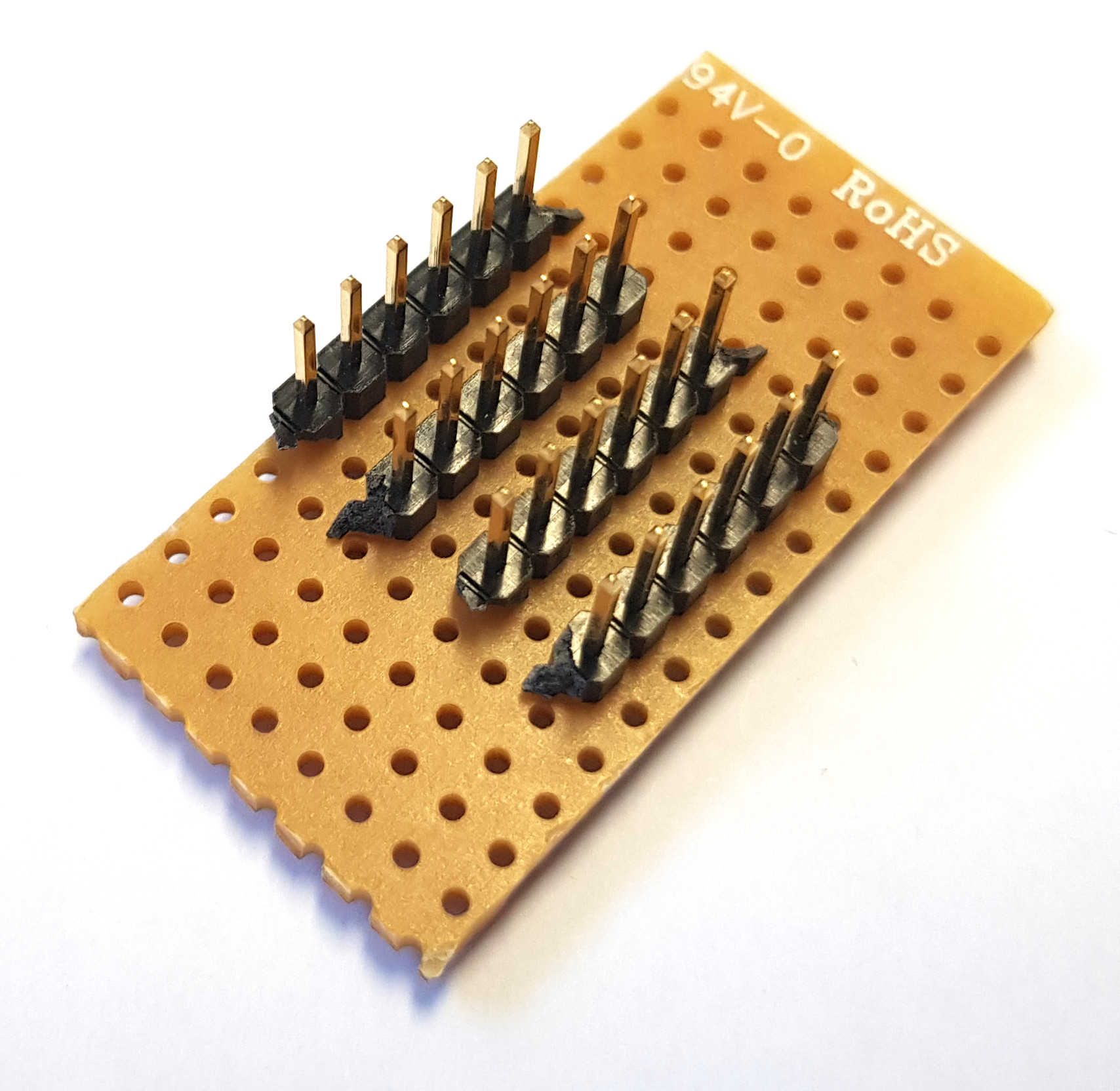
DIY I2C HUB – ready to use
I²C Hub – Material list
Not much is needed for the construction. A metal saw is required to saw the punched strip board and a soldering station to solder the pin strips / connections for the I²C bus on the punched strip board.
Perforated circuit board
Pin header
I²C Hub- structure
First of all it must be clarified how many devices are to be connected to the I²C Hub. I would always count the devices to be installed first. To this number I would add a conclusion for the I²C bus to the Raspberry Pi. Since the biggest work is the cutting of the tape board I would now add five more connectors. This way you are flexible later and can expand your robot car without any problems.
| Description | Number of connections (length) |
| Planned devices: | 5 |
| Connection to Raspberry Pi | 1 |
| Buffer for further devices | 5 |
After calculating the number of connections with 11, we need a punched tape board with 11 holes in the length and four in the width. The four holes in the width are needed once for the I²C bus and once for the power supply.
| Description | Number of connections (wide) |
| Power supply Vin | 3,3V |
| GND | GND |
| I²C Bus data line | SDA |
| I²C Bus clock | SCL |
This results in a matrix of 11 x 4 holes which must be cut out of the perforated strip board. It is important that there are four long rows of holes, where the individual holes are connected by a copper strip. With my Hub I left six connectors and some space to drill four holes into the board to be able to screw it to the robot car.

I2C Hub Lochstreifenplatine
How large the stroke should be can be decided according to individual needs. Furthermore I still left a punched tape between the individual pin rows free. So I have more space when plugging the jumper cables with my fingers.
Note: With too many devices it can happen that an extra power supply with 3.3V must be provided.
In my case the preparations with the pin headers and the sawn out circuit board now look as follows.
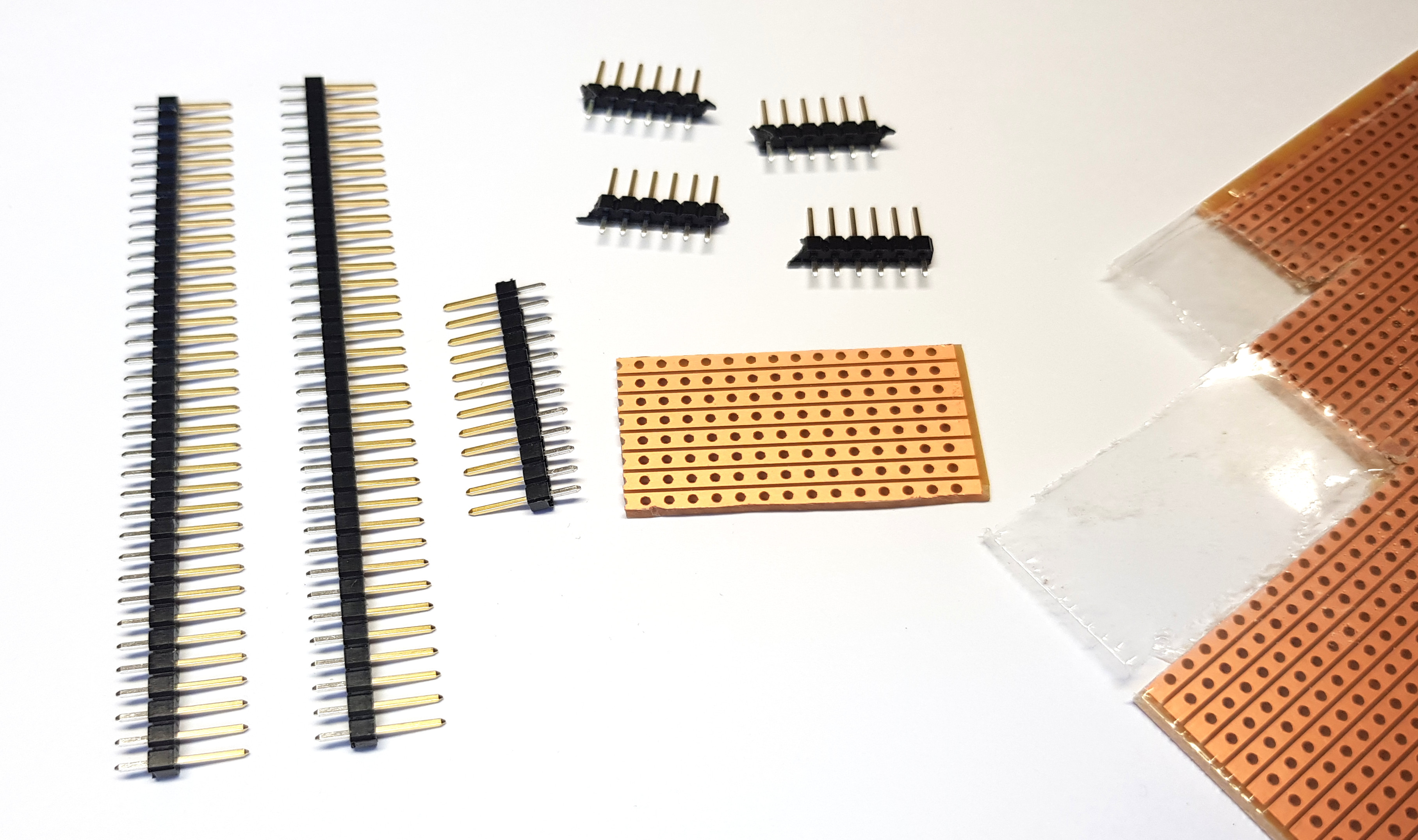
DIY I2C HUB – components
After the small board is cut out, only the pin strips have to be soldered on. Now you have to use a flat nose pliers to break off small pin strips from the long pin strip which are 6 pins long. So you need 4 x 6 pins long pin strips.
I²C Hub – solder on pin header
After you have cut the punched tape board and prepared the 4 pin headers with the length of 11 pins, the soldering can begin.
A little tip: Always solder a pin to the pin strip board of the pin header first and check the vertical fit of the pin header. If this was soldered on at a 90° angle to the punched tape board, you can solder on all other pins from the opposite side.
The following picture shows my procedure with one solder point per pin header.

DIY I2C HUB – sodlering
After you have soldered the four pin headers your I²C Hub is ready and you can install it in your robot car or project.
In my case, the I2C Hub shown above looks like this, ready mounted on my ventilator.
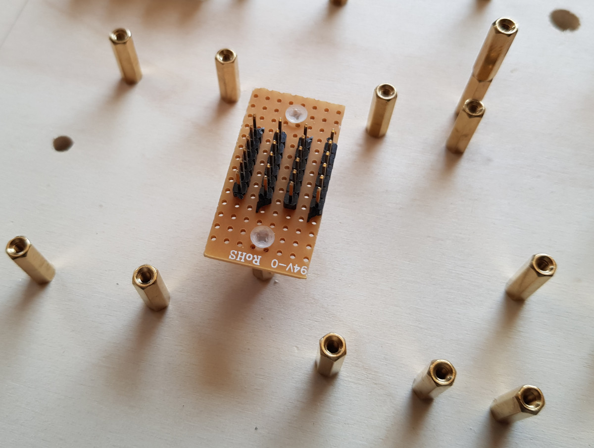
I2C HUB mounted
Summary
It is quite easy to build an I2C Hub yourself. The only important thing is that you use a pin strip board and that you have the right pin headers. Then you can build your own I2C hub very fast and you are extremely flexible when connecting I2C devices in your robot car. The costs are also manageable and amount to less than five euros.


Recent Comments