


For the construction of the chassis of the OpenBot robot car I use the 4WD Smart Car chassis instead of 3D printing. I decided to go this way because I don’t have a 3D printer and I believe that this solution leads to the same result but costs less. I have also had very good experiences with this chassis and have used it in several robot car projects. Also these acrylic glass plates can be transferred very easily to cardboard. So you can get these carrier plates from cardboard very fast and you can put great superstructures on them again with cardboard. But more about this in this article and yes, some creativity is now required.
The following picture shows two of these acrylic glass plates, the motors with wheels, the Arduino Nano, the L298N motor driver, the ultrasonic sensor and a bag with the screws and spacers that are always included with the 4WD chassis. Further a stable cardboard is needed, for example a clean vegetable crate from the supermarket.
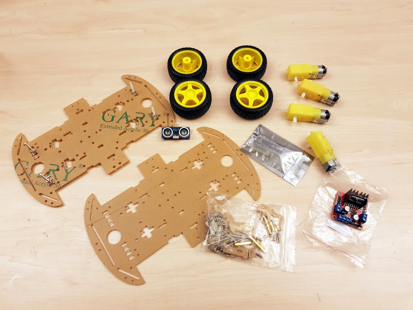
OpenBot chassis build 4WD Smart Car
4WD Chassis Assembly
First the power cables are soldered to the four motors. It is a little easier to take the motors out of the yellow housing. Then you don’t burn the plastic or the loop that holds the motor in the gearbox with the hot soldering iron.
After the cables are soldered to the motors, the assembly continues. The protective foil on the acrylic glass can be removed quite well if you first warm it up with hot air from a hair dryer and then remove it. Afterwards the motors are fixed on one of the acrylic glass plates with the included brackets. The motor driver and the Arduino Nano can be fixed quite well on the acrylic gals with cable ties. I fixed both components on a piece of cardboard later during the project.
The following picture shows the mounted motors and the Arduino Nano mounted on a piece of cardboard. Later I mounted the motor driver and the Arduino Nano together on a piece of cardboard which has the same shape as the acrylic glass plate.
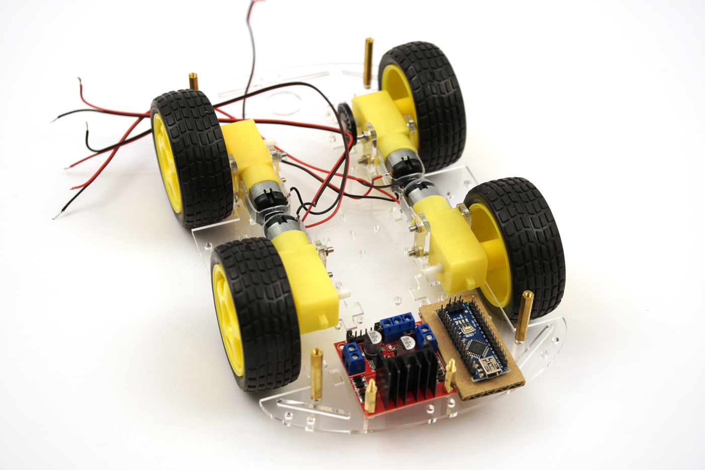
OpenBot chassis build DC gear motors and electronics
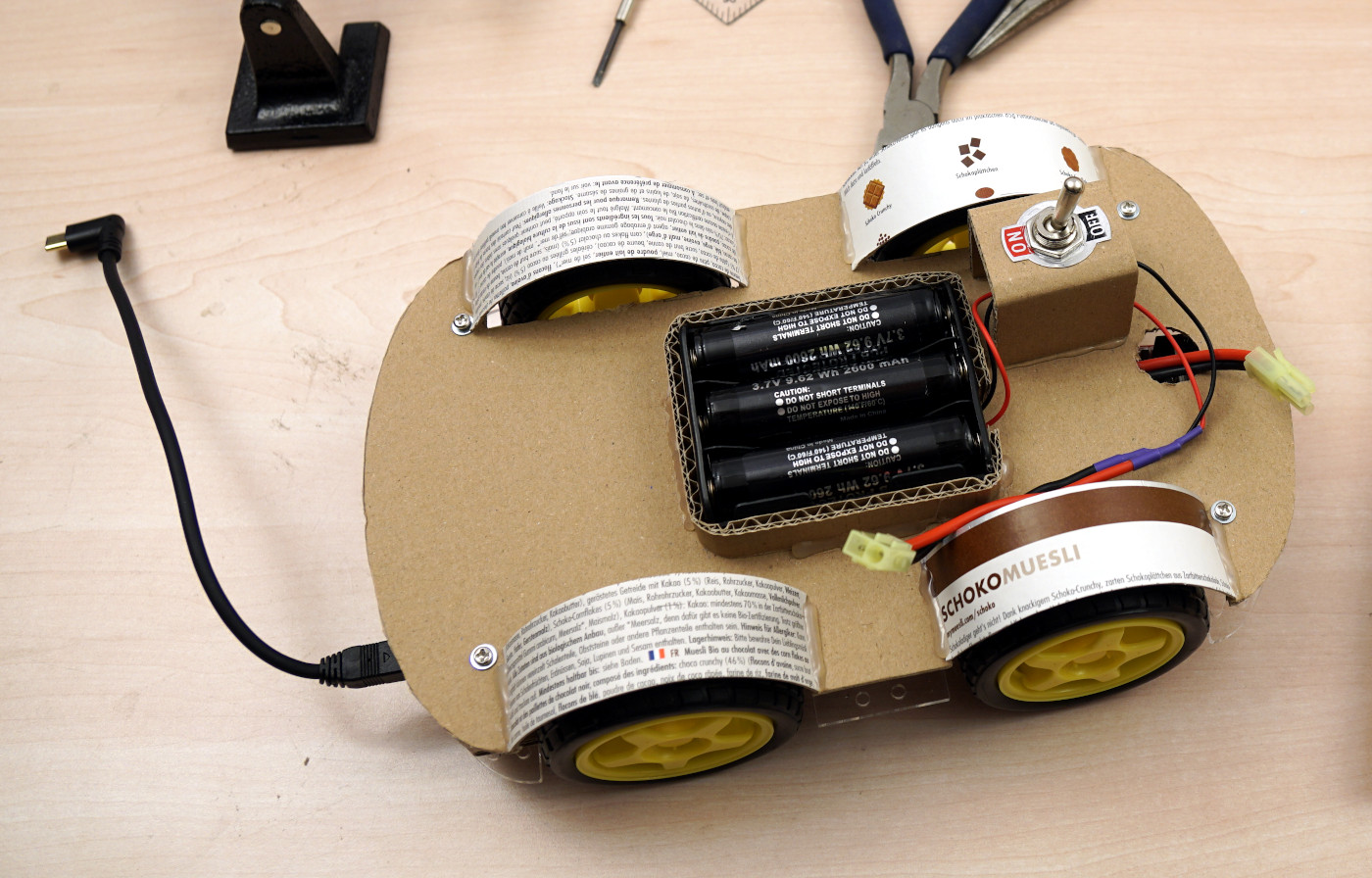
The following picture shows the already wired robot car with the two battery alternatives I tested. Unfortunately I had to realize that the operation of the robot car with the power bank was not possible. Nevertheless I wanted to show the picture here for another reason. On the left side of the acrylic glass plate you can see the piece of cardboard on which I mounted the ultrasonic sensor and now also the Arduino Nano. In the center of the picture I built a power distributor for 5V out of a piece of a punched strip board and a matching pin header and mounted it again on a piece of cardboard. So I have access to a 5V source centrally in the robot car. The motor driver on the right side is now fixed with a black cable tie. Before that I filed off the solder pads on the backside to get more space in the height.
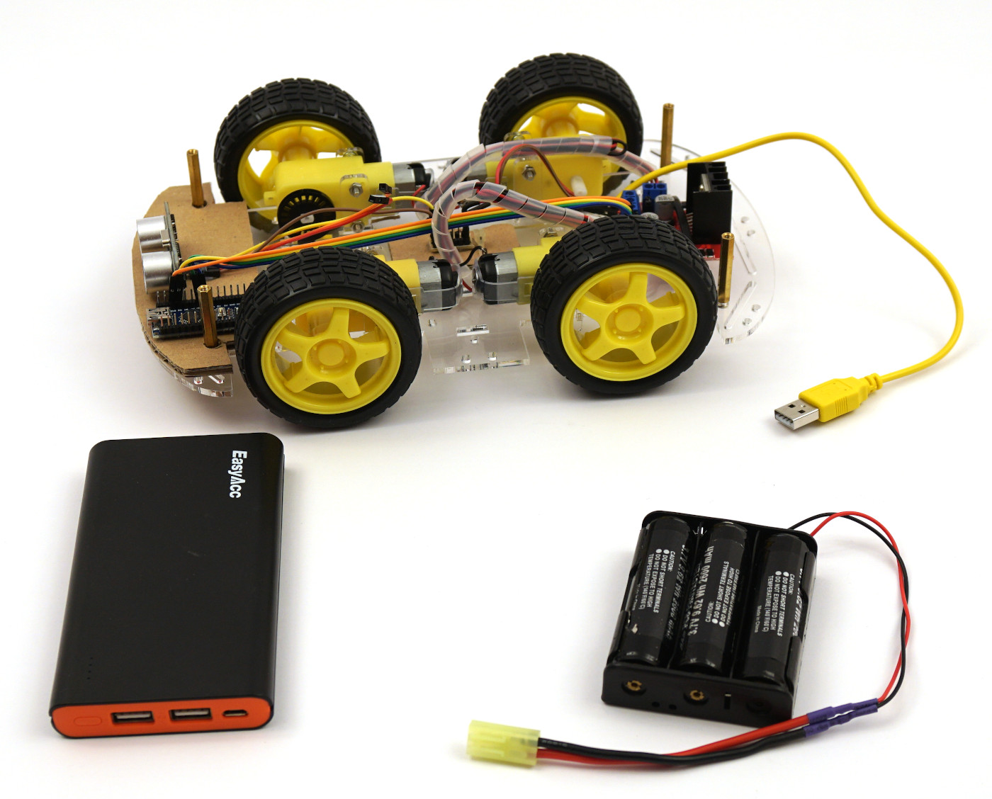
OpenBot chassis build electronics
The following picture shows on the right side a motor driver with the normal solder pads sticking out and on the left side for comparison the version filed off by me to gain space in height.
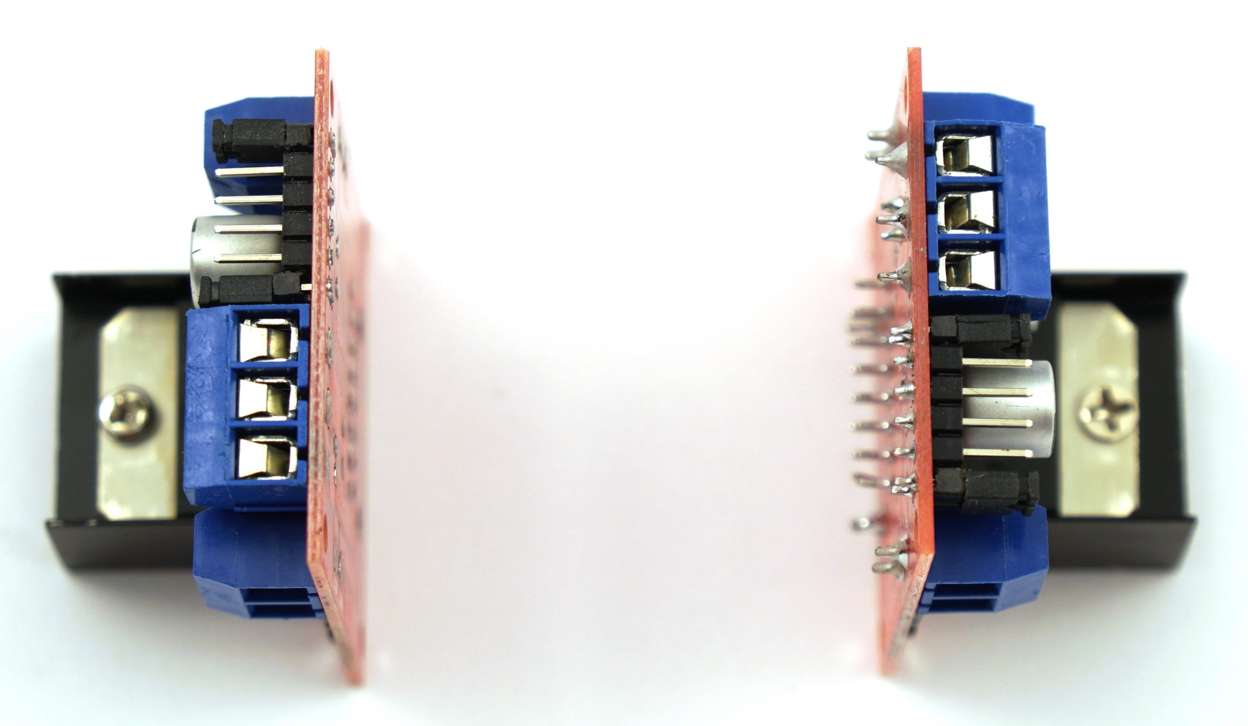
OpenBot chassis build L298 H-Bridge modified
After mounting all the electronic components except the sensors for measuring the engine speed I used the second acrylic glass plate to make a copy out of cardboard without all the holes and grooves. I then mounted it with the appropriate spacers on the robot car. The battery holder and the holder for the smartphone are mounted on this plate. In addition I added the two brackets for the on/off switch and the OLED display.
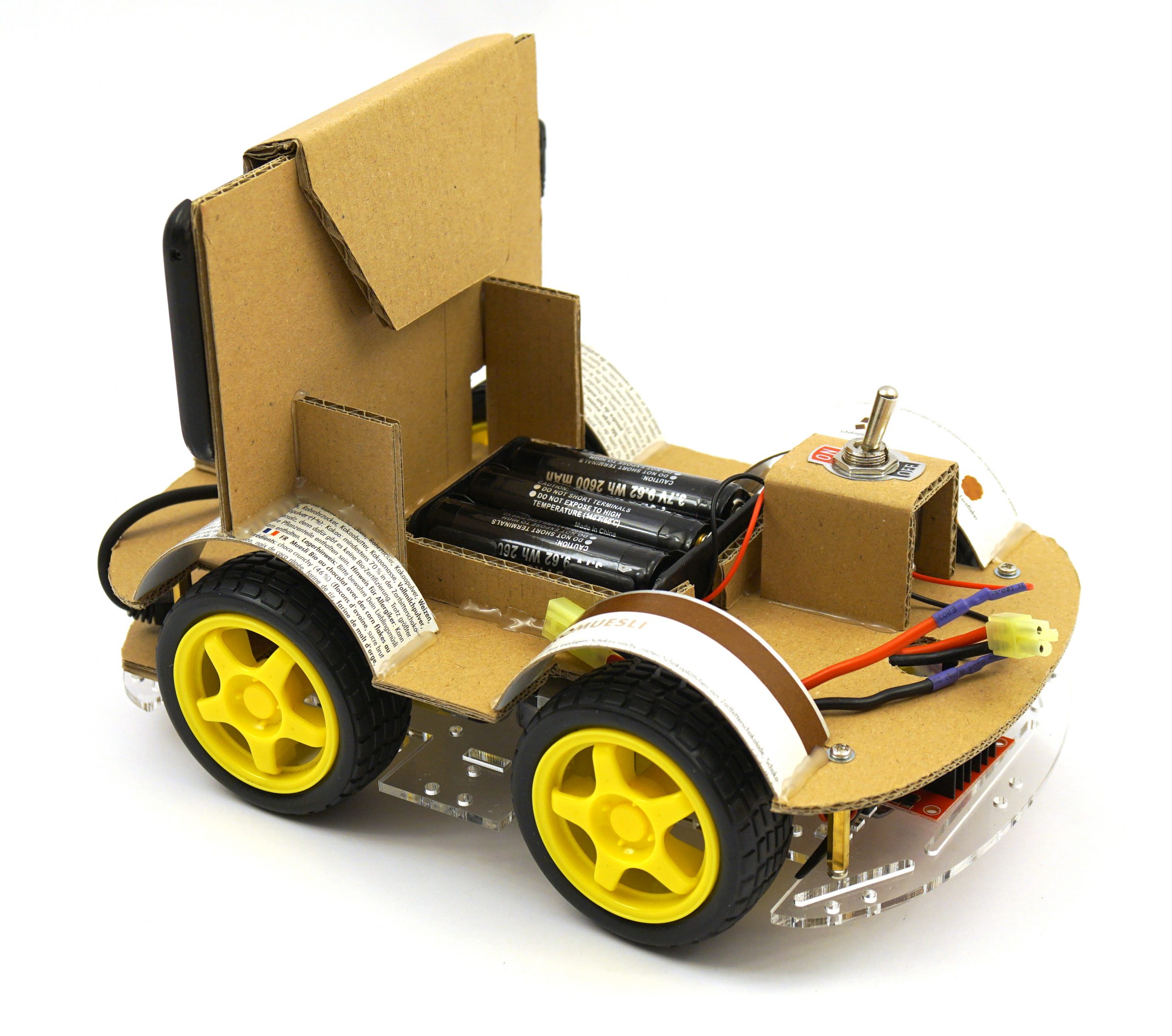
The following picture shows an intermediate stand but already with the nice wheel cases from a muesli box and the battery holder including the on/off switch.
OpenBot chassis build cardboard chassis
Next I built the holder for my smartphone from cardboard. It is fixed between and on the wheel arches. The Smartphone is pushed into a kind of pocket which can be closed on the back of the holder with a velcro.
The picture shows quite well the construction of the holder. It is important that the creases for the cardboard are stamped before the actual folding with e.g. a geo-triangle.
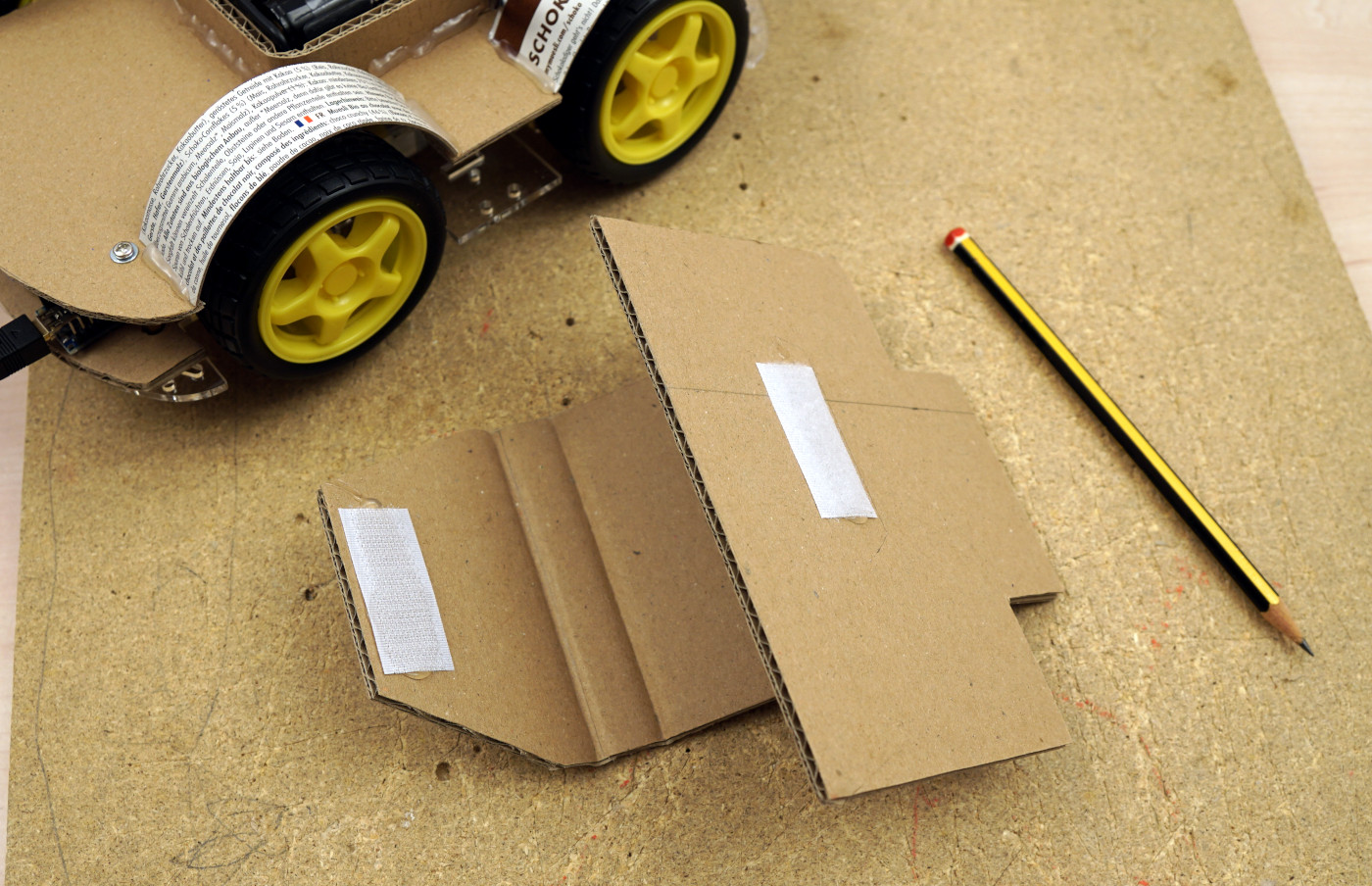
OpenBot chassis build Smartphone holder
Then I fixed the bracket in the front of the robot car between the two wheelhouses. The finished result looks like this.

OpenBot chassis build Smartphone holder mounted
Photographed from behind, the holder for the smartphone with the reinforcements looks like this. I mounted the reinforcements in case the robot car should try to drive under a bed or get stuck on the coach.
OpenBot chassis build Smartphone holder back view
At the end I mounted the holder for the OLED display next to the on/off switch and then the chassis of the robot car was finished. The OLED display is connected in a way that the four cables are extra long so that I can easily remove the upper part of the chassis and put it aside. For the extension I used four female-to-female and four female-to-male jumper cables which I simply plugged together. The following picture shows the holder for the OLED display.
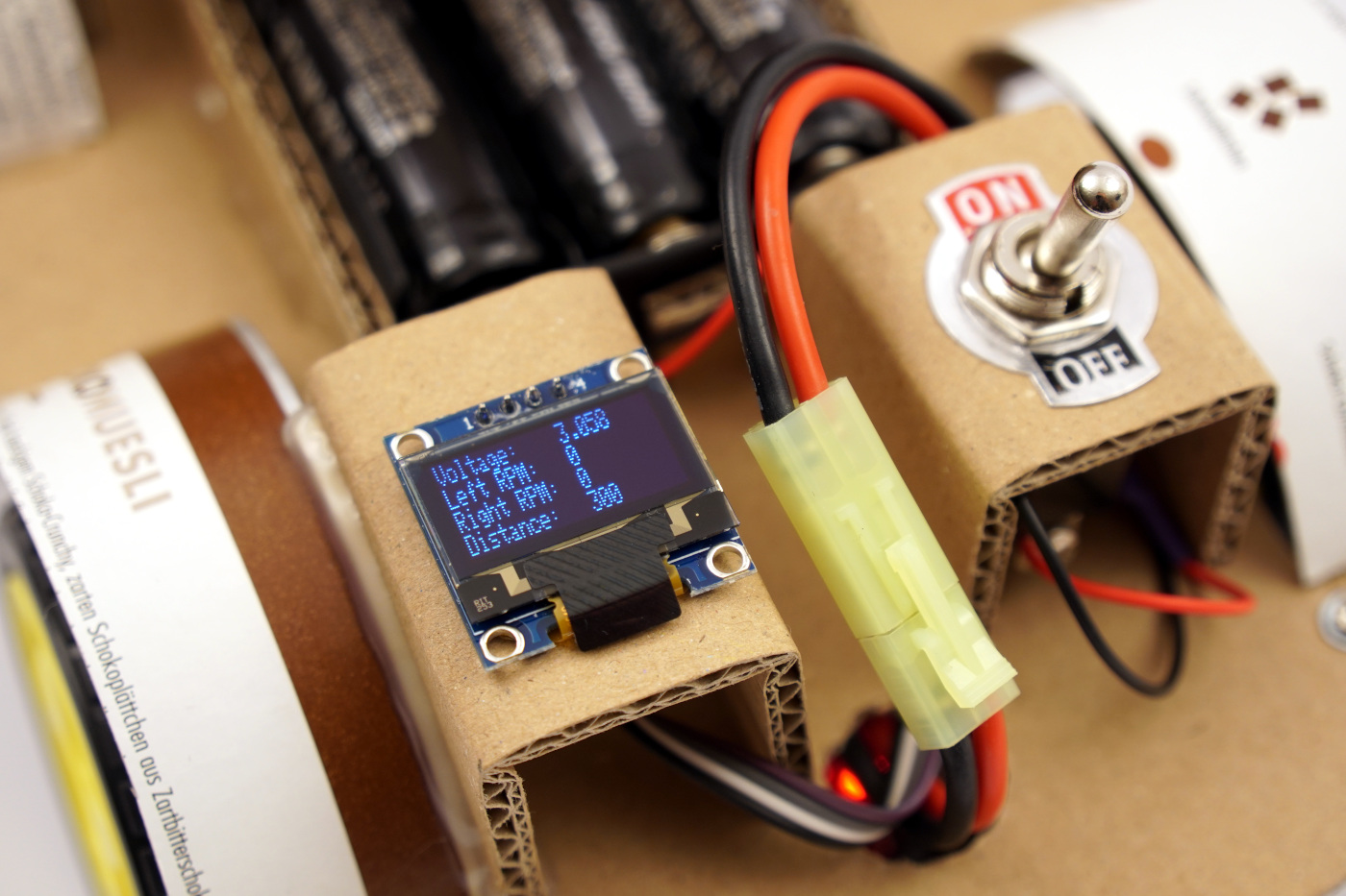
OpenBot switch and OLED display
Summary
I personally always enjoy building a chassis out of cardboard. If you don’t want to do that, you can use the 3D print of the OpenBot. While I was building the cardboard superstructure I had to let the robot car drive over and over again to test if everything works as I imagined it. So that the robot car can drive I will explain the wiring in the following article.
Article Overview OpenBot robot cuto:
OpenBot – Your smartphone controls a robot car – IntroductionOpenBot – Your smartphone controls a robot car – needed parts part 1-2
OpenBot – Your smartphone controls a robot car – needed parts part 2-2
OpenBot – Your smartphone controls a robot car – constructing a chassis
OpenBot – Your smartphone controls a robot car – Wiring
OpenBot – Your smartphone controls a robot car – Flashing the Arduino firmware
OpenBot – Your smartphone controls a robot car – Android App and first test run
OpenBot – Your smartphone controls a robot car – Record training data
OpenBot – Your smartphone controls a robot car – Set up training environment
OpenBot – Your smartphone controls a robot car – train the neural network
OpenBot – Your smartphone controls a robot car – Setting up Android Studio and your Smartphone
OpenBot – Your smartphone controls a robot car – compile your own OpenBot Android app


Recent Comments