


In the previous articles, the ESP32-CAM was discussed in detail. You learned how to connect it to the PC via the USB Serial Adapter and how to install the sample program CameraWebServer. Afterwards we talked about the construction of the robot car and the cabling. Now everything should work technically and so this article is about controlling the motors and printing a text on the OLED display.
To get everything working you have to add two more libraries to the Arduino IDE. These are necessary to control the servo controller and to display a text on the OLED display.
Arduino IDE – Install PCA9685 Servo Controller Library
In order to program the servo controller which in turn controls the motor driver, the appropriate library must be installed. This is called Adafruit PWM Servo and you have to search for exactly this name again.
Note: How exactly libraries can be installed in the Arduino development environment is already explained in detail in the following report Building robots with the ESP8266 development board – Setting up the Arduino development environment.
When installing the Adafruit PWM servo, please proceed exactly the same way as described in the above mentioned article.
The following picture shows briefly the search in the management menu for the libraries. If the correct library was found, please install it by clicking on the button Install now.
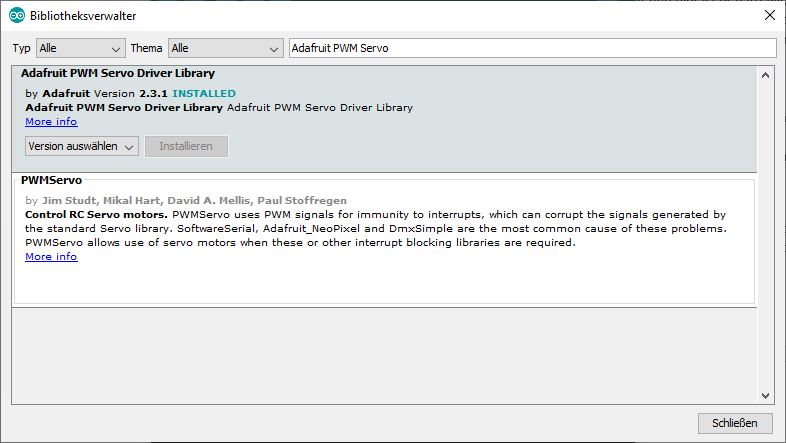
Arduino IDE Bibliothek Adafruit PWM Servo
Arduino IDE – Install OLED Display Library
To be able to access the OLED display from your program, you have to install the necessary library. The same procedure applies here as for the servo controller library.
Please search for the OLED display library with the following keyword “ESP32 OLED” and install it on your PC in the Arduino development environment. Below is a picture of how the search result should look like.
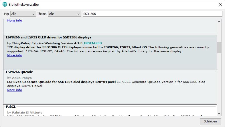
ESP8266 NodeMCU OLED Display SSD1306
From now on you are able to use the two libraries and you can show text on the display or control the servo controller.
Output the current IP address on the OLED display
As a basis for this example, the already known sample program CameraWebServer is slightly modified. At the beginning the library for the OLED display is loaded, some variables for the I2C bus are defined and the OLED display is initialized. Furthermore there is the function “void drawIP(String MyIP)” which draws the IP address to the OLED display. I thought it would be good if the OLED display shows the IP address of the ESP32-CAM to make it easier to call the video stream. The small adjustments are made in the program as far as possible by comments and really only contain a few lines of code.
I wish you a lot of fun trying out the program and maybe adjusting the display according to the position and maybe also the content of the text.
Download: CameraWebServer OLED
Note: An IP address is only displayed if the ESP32-CAM has also connected to a WIFI network. Otherwise nothing is shown in the display. As a small extension of the program, you can, for example, display a message “No WIFI found”.
Starting the engines of the robot car
How the servo controller is controlled you will learn in the following section with the help of a small example program which is documented in the source code. For more information, see the report Building robots with the ESP8266 development board – servo motor control to learn more about the servo controller.
Now follows the download of the small test program that makes the motors of the robot car turn and is based on the previous one to the OLED display. The program only activates the motors and the IP address is shown on the OLED display.
Download: CameraWebServer robo
After loading the program on the ESP32-CAM and resetting it, the robot car should now drive off.
Summary
With this article and the small program adaptations all building blocks are presented so far that the robot can drive a car in principle. Up to now it only drives straight and does not stop because a control is still missing. The missing controller can be realized e.g. via a web interface with a few buttons. One idea I will follow is to adapt the web interface of the program CameraWebServer or maybe to create a complete new program to control the robot out. How it will be implemented you will find out in the next article of this series.
Article Overview ESP32-CAM Robot Auto:
ESP32-CAM building your own robot car with live video streaming – project startESP32-CAM building your own robot car with live video streaming – Set up development environment
ESP32-CAM building your own robot car with live video streaming – USB-serial adapter wiring
ESP32-CAM building your own robot car with live video streaming – Installing the live video streaming software
ESP32-CAM building your own robot car with live video streaming – Design of the chassis
ESP32-CAM building your own robot car with live video streaming – Cabling in general
ESP32-CAM building your own robot car with live video streaming – Wiring the I²C hub
ESP32-CAM building your own robot car with live video streaming – robo car example programs
ESP32-CAM building your own robot car with live video streaming – programming the WIFI remote control
ESP32-CAM building your own robot car with live video streaming – connect external WIFI antenna


Hi,
very interesting project.
Congratulation.
I try implement it in my project with robot arm (PCA9685) but I have problems:
1. when I set sda and scl (Wire.begin(1, 3)) my logic analyzer show no signal.
2. when I set sda and scl (Wire.begin(26, 27)) my logic analyzer show
data correctly on line sda but line scl is still in high level. Scl line should show clock mpulses.
If you can help me pleas write to me whats is happend.
Thank you and Greetings.
Kris.